

Urgent help needed!!!

This site may earn a commission from merchant affiliate
links, including eBay, Amazon, Skimlinks, and others.

Joined
Feb 28, 2005
Threads
20
Messages
93
Location
Down under. Melbourne.
Anyone can explain me please WTF is that (see pic)? Yep, I do know that this is solenoid, problem is I do not know how to connect it. It is clear with big terminals, but I do not understand what to do with small one. Coil appears to be between one of small terminal and eatrh and it draw massive 3.5A - aka small iron. Any input highly appresiated.
Thanks.
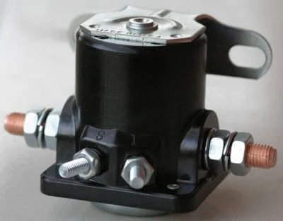
solenoid.webp
 
Yes, it is a solenoid.

The two small terminals are the ends of the coil of the solenoid. By putting a voltage across these two terminals it will connect the two large terminals (to join two batteries together for example).

IIRC there shouldn't be any continuity to earth on any of these terminals.

What application is this solenoid used for?
 
That is a Ford starter Solenoid, used on most Ford products in one way shape or form from the early 60's to present.... although that one looks small for some reason...
 
Mickldo said:
The two small terminals are the ends of the coil
Incorrect, and this is main thing what puzzle me. Solenoid activated when I put voltage between earth and one small terminal ("S" I think) and definatelly does not activated when voltage put across small terminals :confused:
Intended to use in dual battery setup
 
Incorrect, and this is main thing what puzzle me. Solenoid activated when I put voltage between earth and one small terminal ("S" I think) and definatelly does not activated when voltage put across small terminals
Intended to use in dual battery setup

KSV;

Try using an ohmmeter and measure between the two large studs; there should be no continuity.

Then measure between either large lug and the mounting frame [earth]. There should be no continuity.

Then measure the resistance between the two small lugs [the coil], there should be around 3.429 ohms.

Then measure from either small lug to the frame [earth], there should be no continuity. However, u may find a resistance of ~3.4 ohms from the "S" terminal to frame ground [earth] and zero resistance from the other [not "S" terminal] and frame. This means that the (not "S" ) terminal is connected to the mounting frame. This allows mounting of solenoid to a body panel without running a ground wire.

If the solenoid coil is internally grounded to the frame this may be a problem for a dual battery hookup - depends on the schematic of said dual battery arrangement.


...
 
KSV said:
Incorrect, and this is main thing what puzzle me. Solenoid activated when I put voltage between earth and one small terminal ("S" I think) and definatelly does not activated when voltage put across small terminals :confused:
Intended to use in dual battery setup

You got it right the S is the + for the coil and the mounting bracket is the the ground.
Thats how you hook it up. the other small term is used on some older fords as a "boost" for the ingnition system when cranking
The only problem with useing this type (starter) of relay is they dont like to be used as a continuous use unit . It will work for a while but wont last real long (months) .
 
Koffer said:
You got it right the S is the + for the coil and the mounting bracket is the the ground.
Thats how you hook it up. the other small term is used on some older fords as a "boost" for the ingnition system when cranking
The only problem with useing this type (starter) of relay is they dont like to be used as a continuous use unit . It will work for a while but wont last real long (months) .
Thanks for comprehensive info :beer:
You right - I have another one (cheaper construction) and it last only for 6 month or so. I picked this one because it looks better constructed for me. But having coil resistance around 3.5 ohm does not promise long life, because it is equivalent of 40-50 watts! It going to be overheated and doomed :frown:
Any though/suggestions? Can I use for example "S" terminal to activate it and "I" to hold it or something like that?
Thanks again.
 
The I terminal usually is pulled in when S to earth/ground pulls in the big terminals if that is the type of solenoid you have.
Although it has already been covered with other words; the test I do with those solenoids is check continuity from S to bracket. If no, check between S and I. If S to bracket which seems to be your case then + to S and ground the bracket is how the coil has to be pulled in. For a test if that is the case and to see if I gets pulled in, put 12v to S, earth/ground the bracket, and see if you then don’t have 12v at I.
The amps that the coil pulls are not as important to failure as to how the solenoid was designed. For example some solenoids like the NAPA ST551 and maybe ST552 are rated for continuous duty for golf carts, fork lifts, etc. The one you have might be rated for intermittent duty to be energized just long enough to start a vehicle. I ran the ST552 in my cruiser for a couple of years in a dual battery setup and had no problems.
Are there any other numbers on the solenoid? There is a slim possibility I might have a diagram of the solenoid.
It might be best just to buy a better one from Wrangler or Hellroaring and be done with it.

Here is a picture of just a few diagrams of solenoids. Hope this helps.

Bill
Solenoid-Diagrams.webp
 
Koffer said:
You got it right the S is the + for the coil and the mounting bracket is the the ground.

And you really want a fuse on the "S" side of that solenoid.

-B-
 
Back
Top Bottom