

LED dome Light wiring question

This site may earn a commission from merchant affiliate
links, including eBay, Amazon, Skimlinks, and others.

Joined
Sep 13, 2006
Threads
138
Messages
843
Location
Tierra y Libertad
After reading Heckler's post 'Another way to get LED dome lights" https://forum.ih8mud.com/showthread.php?t=131597&highlight=LED I got the 31" 36 LED array lights from autolumination but I got this type in the mail, which looks different than the one on their web site.... As you can see, The 36 LED array wiring ends like this.. The 36LED array shown in the web site looks different....How can I make this work?
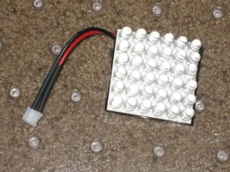
IMG_0039.webp
 
You could buy a few incandescent bulbs, replcae the glass with wood or something else non-conductive and solder the leads in.
 
I got one like that. I got a bulb attachment but it was rectangular instead of round like a bulb. It might work in some sockets but it didn't work in mine. I didn't want it to be flaky at all so I hard wired it in.
You could do that too. Cut the plug off the LED wires and bare the ends of the wire. Test the LED with a battery to determine which is ground and which is hot. It is polarized and won't work unless you know which is which. Then I took the map light assembly off the vehicle. I soldered the ground wire from the LED onto the ground plate for the map light. Then I cut the power wire on the back of the map light and soldered the LED power wire into it. Once that is done the LED array fits nicely up under the clear plastic area for the map light.

I have pictures that I can probably get up tomorrow.
 
That is correct, they did not ship the second pieces...bulb socket attachment..FYI...I only saw email as a form of contact with autolumination...no phone no....a bit weak...

I will wait for autolumation to send the missing pieces before doing the extra work as suggested here (but good advice anyhow.) Cheers. Oh Eric E since you offered, do post pics of how you did it....
 
Here are some pics of what I did.
The first shows how I soldered wires onto my LED (note: I got the Red/green wires backwards...so green is hot and red is ground)
It should also be noted that I used the wires off the light plug to solder to. I could also have cut the plug off and soldered to those.

The second pic shows where I soldered onto the Map Light assembly. The red circle is where I soldered ground. The red arrows show the wire I tapped into for hot.

The last shows the under stde of the assembly where I tapped into the hot wire and soldered it all together.
IMAG0003.webp
IMAG0005.webp
IMAG0006.webp
 
Last edited:
Back
Top Bottom