
Trying to find all the wiring diagrams needed to install my new column has been very frustrating for such a popular mod. Yeah there are tidbits here and there, but a lot of them reference wire colors, which do vary on model to model. So I thought I'd put down everything that I've found in one spot.
The column that I'm installing is out of a '91 Cherokee, yeah I know it's a Heep part, but this Saginaw column is the same as any GM column that's so popular. The thread by Texican on Pirate (Tilt Column - Pirate4x4.Com Bulletin Board) is for a Heep column too, so I'm not too far out using a Heep part!
This will be a living thread as I work through the wiring, so I'll be looking for any feedback as I edit this post and add further info.
Now for a couple of pictures that cover the Ignition switch and the turn signal, hazard, etc switch.

Starting with the 1st picture showing the ignition switch connectors. I'll list what positions the key is in when the wire is at 12v (hot), otherwise I'll describe what it's connected to:
Wire #
1. Start (connect this to the starter solenoid)
2. Start & Run (connect this to the ignition)
3. Accessory & Run (Accessories....)
4. This is the Battery connection bringing power into the switch.
Note (the two empty connections to the left of #4, in the
blue connector, are connected to #4 directly)
5. Run (connect this to power anything in the Run state)
6. Start position switches this lead to ground
7. Start position switches this lead to ground
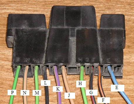
The second picture shows the connector used for the turn signals, hazards, horn, etc. Again I'll list what's connected to what.
Letter:
E. Connected to "F" when the ignition key is in Run, Acc, Start
F. See "E"
G. Horn, connected to ground when horn button is pressed
H. Left Front Turn Signal, connected to the Turn Flasher input, "L",
when the turn signal stalk is pulled down, or connected to the
Hazard Flasher "K" when the flasher button is pulled
J. Right Front Turn Signal, connected to the Turn Flasher input, "L",
when the turn signal stalk is pushed up, or connected to the
Hazard Flasher "K" when the flasher button is pulled
K. Hazard Flasher input
L. Turn Flasher input
M. Left Rear Turn Signal. See "H" above
N. Right Rear Turn Signal. See "J" above
P. Stop Lamp Switch (not used on the Cherokee)
My Turn Signal & Hazard Light solution deletes the stock Hazard switch and and stock flasher unit. I don't like the stock flasher location, and I'm not sure if my big hands could even reach it if I ever needed to replace it. This solution uses two very standard Trico flashers that can handle 1 to 10 lamps each. This way if the turn signal flasher goes bad, you can substitute the hazard flasher in until a new one can be purchased at most any autopart joint for way less than $10. The Turn Signals will get their power from the stock Turn Signal buss found on the fuse block, and the Hazard Lights will get there power from the Stop Light buss on the fuse block. This will allow the Hazard Lights to work at all times, and the Turn Signals will only function when the key is on.
1. Remove stock Hazard Switch (unplug)
2. Hook up 2 Trico EL12 flashers as shown below
3. Connect Contact “H” up to the Left Turn Signal wire in the FJ40 Harness
(For my ’77 this is the Green with a Black stripe wire)
4. Connect Contact “J” up to the Right Turn Signal wire in the FJ40 Harness
(For my ’77 this is the Green with a Yellow stripe wire)
The stock wiring (GB & GY wires) are already connected to the front and rear turn signal lights, along with the indicator lights. So the “M” and “N” contacts on the new column are not needed.
I'll stop for now, and will be adding in the future how I'm going to wire the headlight dimmer connections as well. Please provide any and all feedback.
Jeff

The column that I'm installing is out of a '91 Cherokee, yeah I know it's a Heep part, but this Saginaw column is the same as any GM column that's so popular. The thread by Texican on Pirate (Tilt Column - Pirate4x4.Com Bulletin Board) is for a Heep column too, so I'm not too far out using a Heep part!
This will be a living thread as I work through the wiring, so I'll be looking for any feedback as I edit this post and add further info.
Now for a couple of pictures that cover the Ignition switch and the turn signal, hazard, etc switch.

Starting with the 1st picture showing the ignition switch connectors. I'll list what positions the key is in when the wire is at 12v (hot), otherwise I'll describe what it's connected to:
Wire #
1. Start (connect this to the starter solenoid)
2. Start & Run (connect this to the ignition)
3. Accessory & Run (Accessories....)
4. This is the Battery connection bringing power into the switch.
Note (the two empty connections to the left of #4, in the
blue connector, are connected to #4 directly)
5. Run (connect this to power anything in the Run state)
6. Start position switches this lead to ground
7. Start position switches this lead to ground
The second picture shows the connector used for the turn signals, hazards, horn, etc. Again I'll list what's connected to what.
Letter:
E. Connected to "F" when the ignition key is in Run, Acc, Start
F. See "E"
G. Horn, connected to ground when horn button is pressed
H. Left Front Turn Signal, connected to the Turn Flasher input, "L",
when the turn signal stalk is pulled down, or connected to the
Hazard Flasher "K" when the flasher button is pulled
J. Right Front Turn Signal, connected to the Turn Flasher input, "L",
when the turn signal stalk is pushed up, or connected to the
Hazard Flasher "K" when the flasher button is pulled
K. Hazard Flasher input
L. Turn Flasher input
M. Left Rear Turn Signal. See "H" above
N. Right Rear Turn Signal. See "J" above
P. Stop Lamp Switch (not used on the Cherokee)
My Turn Signal & Hazard Light solution deletes the stock Hazard switch and and stock flasher unit. I don't like the stock flasher location, and I'm not sure if my big hands could even reach it if I ever needed to replace it. This solution uses two very standard Trico flashers that can handle 1 to 10 lamps each. This way if the turn signal flasher goes bad, you can substitute the hazard flasher in until a new one can be purchased at most any autopart joint for way less than $10. The Turn Signals will get their power from the stock Turn Signal buss found on the fuse block, and the Hazard Lights will get there power from the Stop Light buss on the fuse block. This will allow the Hazard Lights to work at all times, and the Turn Signals will only function when the key is on.
1. Remove stock Hazard Switch (unplug)
2. Hook up 2 Trico EL12 flashers as shown below
3. Connect Contact “H” up to the Left Turn Signal wire in the FJ40 Harness
(For my ’77 this is the Green with a Black stripe wire)
4. Connect Contact “J” up to the Right Turn Signal wire in the FJ40 Harness
(For my ’77 this is the Green with a Yellow stripe wire)
The stock wiring (GB & GY wires) are already connected to the front and rear turn signal lights, along with the indicator lights. So the “M” and “N” contacts on the new column are not needed.
I'll stop for now, and will be adding in the future how I'm going to wire the headlight dimmer connections as well. Please provide any and all feedback.
Jeff
Last edited: