Builds White Lightning's Diesel Conversion - A 1994 T100 OM606 swap (2 Viewers)

This site may earn a commission from merchant affiliate
links, including eBay, Amazon, Skimlinks, and others.

Joined
Mar 31, 2017
Threads
2
Messages
100
Location
Blacksburg, Va
So after many years of talking about, lurking through forums, and frankly annoying even myself with all talk and no action, I finally bit the bullet and started the swap process. I knew I wanted a diesel engine in the truck, partially for mileage, partially for cool/sound factor, so everyone (including me) whose thinking "An LS swap would have been easier and more power" can keep those comments for another thread ;) . I landed on the Mercedes OM606 due to availability (found a wrecked donor vehicle local), power, reputation for robustness, and also the fact that it's an I-6, which should mean it'll be a lot smoother than the rattley 4 cylinder diesel options.

The Truck for starters is a 1994 Toyota T100 4x4 thats been in the family since 1995, so it's got some sentimental value to it. The 3.0 in it never let me down except any time I had to go up a hill with something in the back. Here is a picture in it's pre-swap state. It's got 1.25" Ball joint spacers up front, Bilstein 5100 shocks all around, a Kazuma LSD, and sits on BFG AT 31" Tires (almost as stock as they come at this age).

20170122_124951.jpg

Here is the new engine/trans coming home (in my dads Tundra). It came from a wrecked 99 Mercedes 300d. It came with all ecus, exhaust, intercooler, and any wiring I could cut out of it before he hauled it to the crusher. The plan from the start is to sell the Mercedes trans and make an adapter plate to keep the original Toyota R150. For fuel control I've ordered and received Baldurs ecu (A guy in Iceland? who has made his own ecu for the om605/6 engines). I highly considered going with the mechanical pump route, but decided against it. I've done a fair amount of gas fuel injection tuning on another car of mine and figured it would be fun to do the same on this.


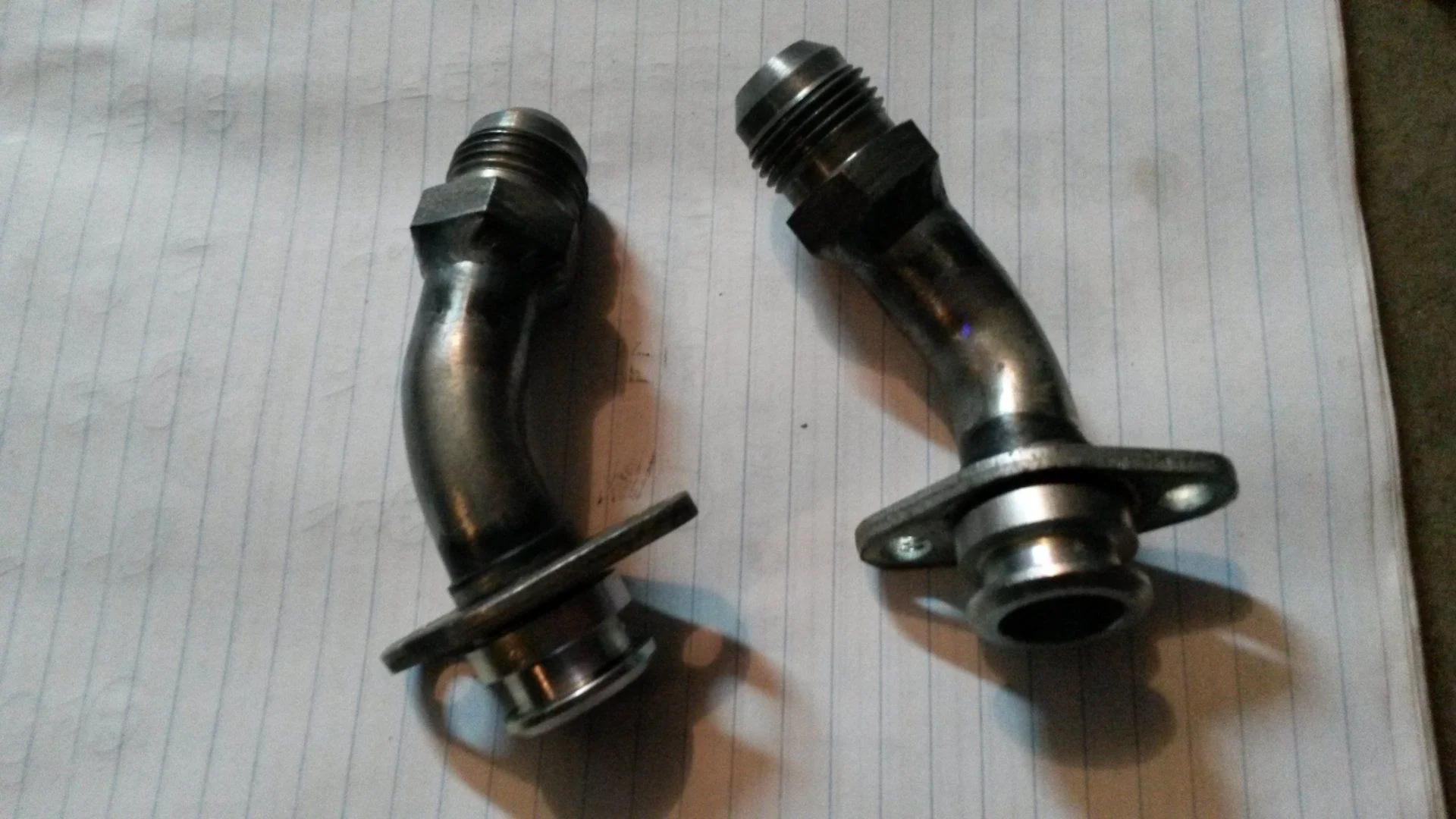
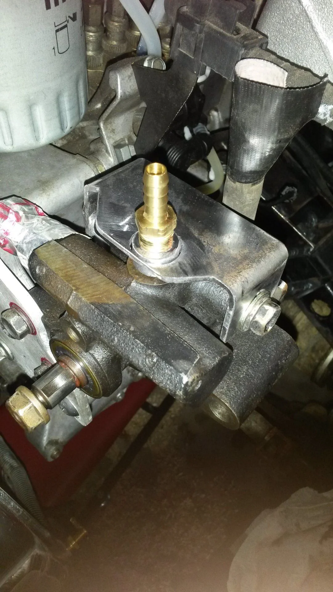
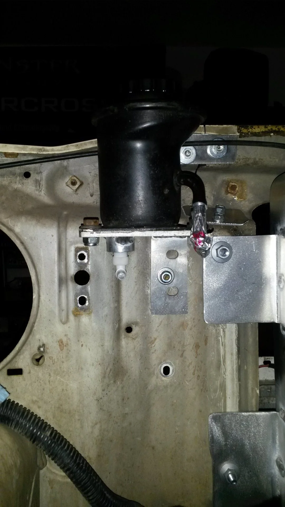
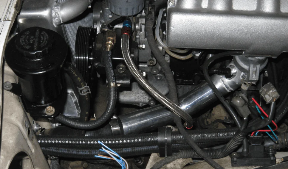
Did a little cleanup on the engine, replaced the plastic fuel lines, cleaned the EGR gunked up intake and replaced some gaskets that looked to be leaking. You may notice the power steering pump is off in the picture. The pulley was damaged in the wreck so i've had to order a new one. Additionally I'm planning to mount the original toyota pump as the mercedes pump runs a higher outlet pressure (~1800psi vs 1400).

20170121_174850.jpg


20170121_155209.jpg


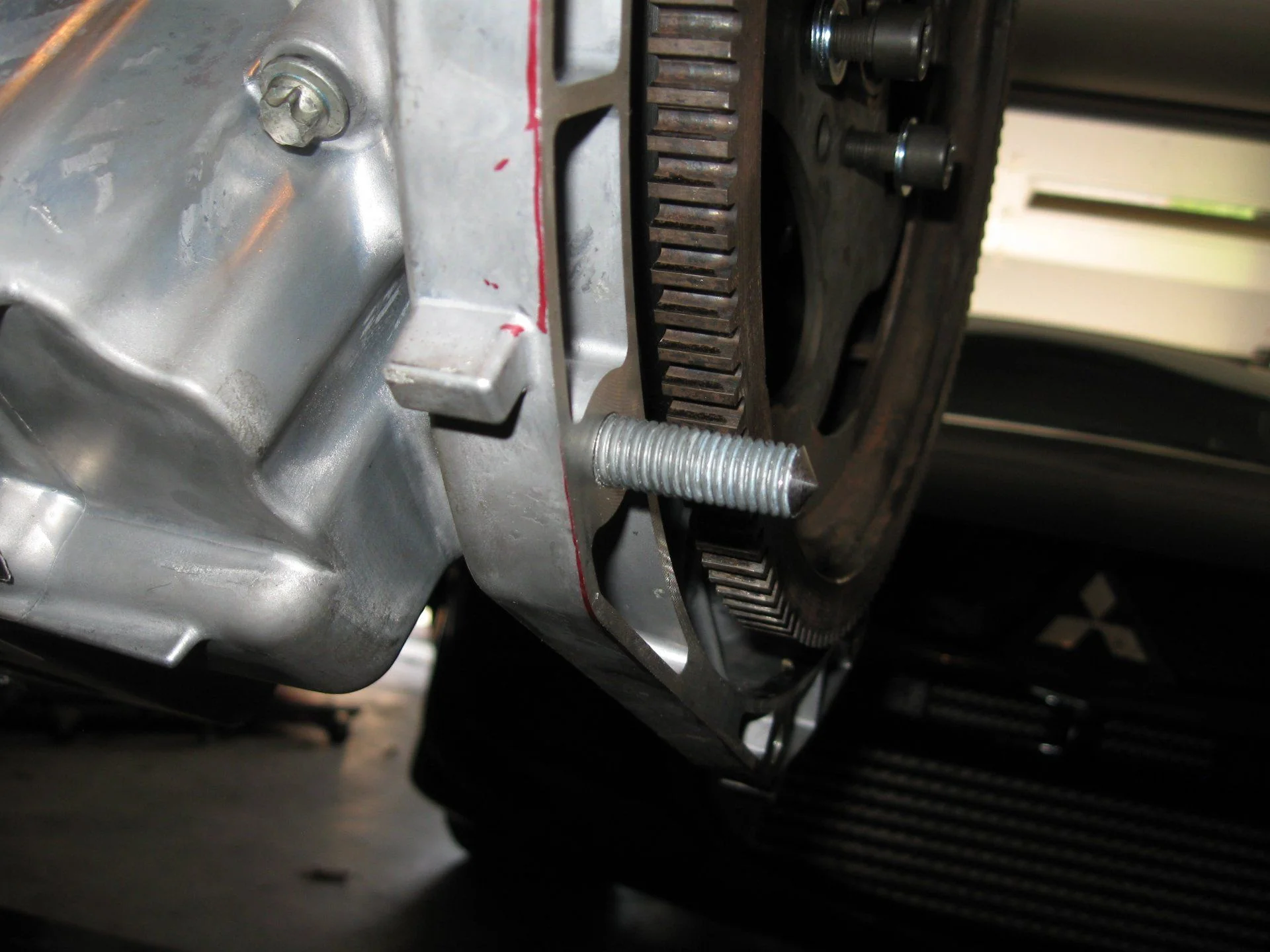
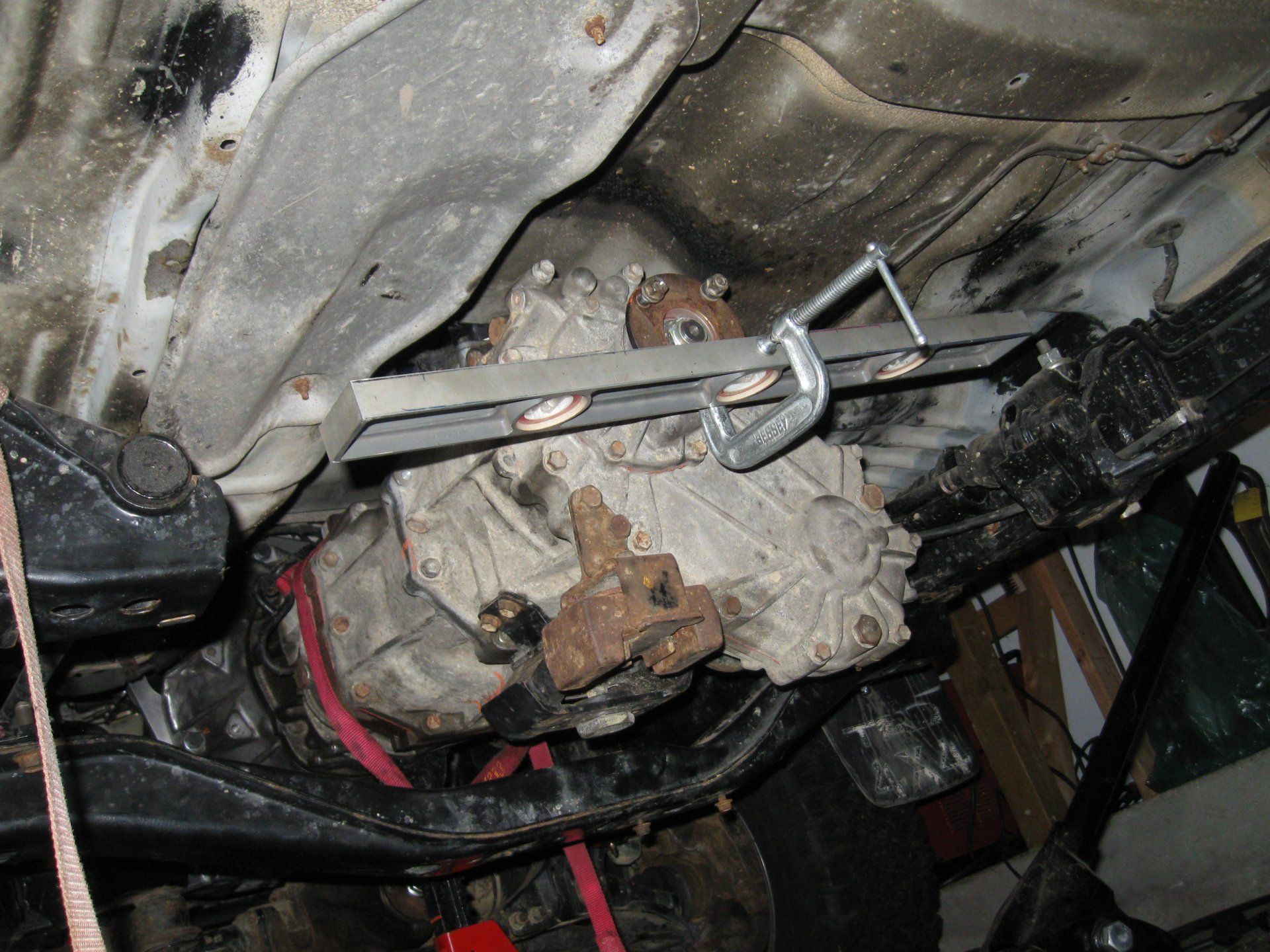
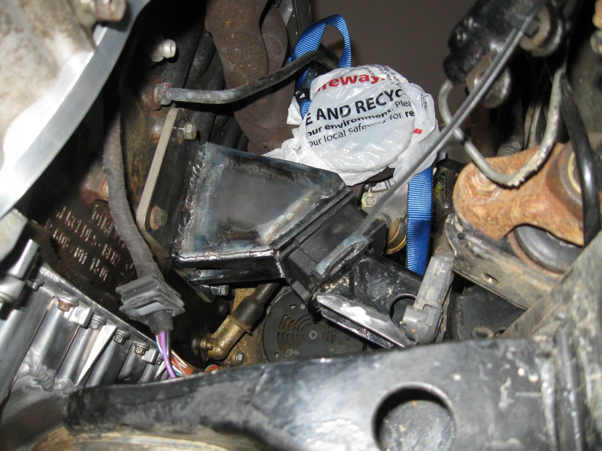
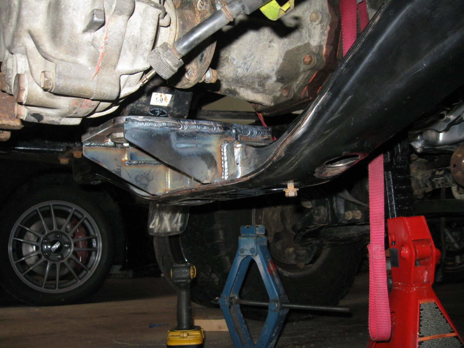
Started the Teardown on the truck, took lots of angular and positional measurements referenced to the frame so I can get things back at the right angles at least. It's looking like i'll need to slide the trans back about 4" to fit this behemoth behind the front core support. Before I did any teardown I put it on some scales with 3/4 tank of gas to get a weight distribution (man this thing is light!). I wanted too see how much the new engine changes it. Currently the truck has very good on road handling, which I assume is because it's so light, and the majority of the engine is behind the front axle. The OM606 is probably about 100 lbs heavier than the 3.0 coming out from numbers I've seen online (om606 ~490, 3.0 ~375)


"here is your new home transmission"

20170128_173542.jpg


Started work on the adapter plate. Fortunately I was able to find dowel to crank centerline patterns for the OM606 and the toyota R150 posted online, which saved me a ton of time. The om606 came from the super turbo diesel forum and I believe the R150 came from this one... i forget the username, will update later, but THANK YOU! I sketched them out in CAD and then printed them on paper to fit check them.


Last edited:
This is the mercedes flexplate. The plan is to use this to keep the trigger wheel and ring gear positions as is. I'll then make an adapter to add the toyota flywheel. I went and bought a toyota 3.4 flywheel and clutch kit as I'd read the 3.4 was supposed to have a larger disk. Side to side the disks appear the same. The 3.4 flywheel is clearly heavier. Guessing the 3.4 pressure plate has higher clamping force.

20170204_210156.jpg


Toyota 3.4 flywheel infront of Mercedes Flexplate. Ring gear diameters are almost the exact same. Both use an 8 hole bolt pattern (!) with a pitch circle only off by ~2mm in diameter. I'll just mill a 1mm slot in the right direction on the toyota flywheel. I've made a cad assembly of the engine, flexplate, adapter, toyota flywheel, clutch disk and transmission in order to get the axial spacing right. I'll add a cross section view in a later post.


here is the first (not) fitting of the engine. Ran into multiple issues. 1) not enough room for the radiator, will need to move the trans back, but can't do that because the body is in the way, guess that means a body lift is on order, 2) can't drop the engine down far enough - the front pan runs into the steering rod, guess that means I need the 400$ rear sump oil pan (read about this being needed in other 4x4 conversions).

IMG_0909.JPG


IMG_0905.JPG


IMG_0904.JPG


Got the 3" Body Lift Kit in from Performance Accessories. The T100 body always sat low, I like the look of it higher, although I think I'd rather it be a 2" Lift (they only sell 3" now). (update - have replaced the spacers with 2" ones, things just barely fit) PS the lift is just on the cab for now, the bed is going to require me cutting out all the old stuff with an angle grinder...so thats gonna happen outside at a later date

20170225_121328.jpg
 
Last edited:
Finished taking measurements and designing the adapters. Made a few representative CAD models of the OM606 block and R150f transmission for fit checks.

Assembly.JPG


Mainly used this model to figure out how thick the adapters needed to be to get the clutch in the right place axially on the transmission input shaft.
Cross Section of Assembly.JPG


View of the adapters. The orange is the om606 flexplate. The plate is currently missing the om648 oil pan bolt holes. Once the plate is made i'm going to use transfer punches and drill those 4 holes myself. I was able to get the transmission and engine clocked to their original resting angles with only a few modifications. I'll document those later on. nonetheless the bolt patterns are very close and overlap on a few holes no matter what, so i've had to relocate a hole or two.

Adapters.JPG
 
Last edited:
Got the plate and the flywheel spacer in from a machine shop up the street. With access only to a wobbly lathe and a glorified drill press I was more than happy to fork a little money to these guys, primarily on the flywheel adapter due the tolerances needed. The plate is 5/8" 7075 Aluminum and the adapter is just some mild steel they had on hand. On the adapter plate I had them just put in the dowel holes + the bolt holes I knew the location of (everything but the om648 oil pan holes). I tapped and helicoiled the holes for the transmission since they were going into aluminum. The Toyota uses 6 M12 bolts and 4 M10s. I was able to get 5 of the M12s and 2 of the M10s in there without overlap with some feature of the Mercedes pattern. I will weld additional bosses to the bellhousing for these (in locations denoted by the circular additions around the adapter).
IMG_1310.JPG


The plate was designed to be machined from one side, 1 to make it cheaper, 2 to keep the dowel locations between the engine and transmission as aligned as possible. Some angle grinder work on the starter side by the dowel was required for everything to fit. Also for the starter, I threaded the adapter plate and bolted to it from the engine side with some gr12.9 allen head m8 bolts (originally its threaded and gets clamped against the engine from the transmission side with m10s). If I hadn't done this I would have had to unbolt the transmission to replace the starter, and there was interference with one of the dowel holes for the toyota transmission, so this had to happen.

IMG_1307.JPG


slotted the toyota flywheel bolt holes on the mill, it's amazing how close the toyota pattern was with the mercedes.

20170111_211706.jpg
 
Last edited:
Made this little guy on the lathe to get the one om648 oil pan hole I couldn't get to with a transfer punch


Plate and flywheel mounted - ready? for the transmission install. If your wondering why the color of the pilot bearing changed, it's because the first one I did felt a too tight so I opened up the press fit a hair. Turns out they aren't meant to take much of an interference fit, (if anyone actually needs to replicate this, the bearing was a 32.00 OD, and I made the adapter to 31.98ish and installed the bearing with the green loctite retaining compound. Initially I had it at 31.7 which was wayyyyy to much, as was 31.85).

IMG_1316.JPG


IMG_1320.JPG


And the moment of truth....phew it actually lined up. I still need to confirm where the clutch disk rests on the splines,

IMG_1328.JPG


All together. The assembly from the driveshaft flange to the pulleys is 68.75"

IMG_1324.JPG


IMG_1327.JPG
 
Last edited:
with this thing bolted together, it was time for some fit checks. As expected, the oil pan was going to need some clearancing for the front diff and some for the front diff mount. Also the drain plug was going to need to get moved. The good news is this is the first time i've been able to fit the radiator in there. It's looking like I'll have to go with a pusher fan on the front though for sure.

IMG_1337.JPG


IMG_1338.JPG


Nothing like taking an angle grinder and sawszall to your brand new 380$ oil pan. Here is it welded up, and the drain plug relocated. I set the pan at the angle I think it will end up in the car then added some water to made sure the plug location won't leave a puddle in there. I also welded the hole for the "oil condition/level/everything" sensor as I have no use/ability to read it...and I don't have one. Welding it took a little while as I only did small sections at a time to make sure I didn't warp anything. Also having an air cooled torch helped make sure I wasn't welding too long as it got really hot reallly quick (was basically running 125-150amps to get any sort of puddle going).

IMG_1342.JPG


Next I filled it with water over night to leak test it. Found no leaks...so we'll see how it all holds after a few heat cycles. I then reset it at the angle I think it will sit in the car and added 8 quarts of water. since I can't find a freakin dipstick for this thing (-1 for Mercedes on that) , i'll likely be making my own and I need to get a decent idea what "full" should be (I can't even get a dipstick tube as they discontinued that and ebay has been empty). I was also curious what 8 quarts looked like relative to the oil pan mating face, it's basically right at the line

IMG_1349.JPG


Back in with the new pan. I think it's sitting where i'll leave it. It's essentially 1 2x4 section above the toyota mount arms
IMG_1357.JPG
 
Last edited:
There is just enough room to get the bellhousing up and on there with the clearance to the body. I'd love to take out the 3" body lift spacers and use some 2" ones, but i'm pretty hesitant due to the minimal clearance I have here.

IMG_1359.JPG


Way more clearance to the firewall than I had expected. Lots of access (and room) around the turbo incase I decide to go with something a little larger down the road

IMG_1339.JPG


IMG_1363.JPG


IMG_1341.JPG
 
Last edited:
Still working through the engine mounts. Planning to use these first Gen Cummins mounts (orginally for the Dodge ram) on the stock Toyota perches. I've gotten some plate to bolt to the block so I "just" need to get the engine in it's final position and then connect the plate to the mounts. I'll probably weld in a support for the frame perch as the cardboard in the picture suggests.

IMG_1376.JPG


I was able to get the om606 "TPS sensor" mounted/mated with the Toyota throttle cable. I used the throttle actuator off the toyota intake and then spaced it on the TPS such that the cable pull matched 0-100% on the sensor. It's not the prettiest mount I've made, but it's quite functional.

IMG_1380.JPG


IMG_1382.JPG
 
Last edited:
Finally got around to getting the engine in it's "final" resting place and making some mounts. I decided on first Gen Cummins isolators and then fabbed the mounts from scratch. I started with the 5/16" plate on the engine and a 3/16" plate on the isolator. I positioned the engine such that the toyota transmission rested at the same roll and pitch that it sat originally. This correlated to the engine being tipped back roughly 3.5° which is good for the rear sump oil and and is pretty close to the 3° rule of thumb. I squared everything up taking measurements between a frame cross member and the transmission output flange. This also seemed to make the pulleys at the front square with the frame and radiator...so I went with it.

IMG_1397.JPG


IMG_1386.JPG


It was way easier to get the camera in to take this shot than it was to tack weld these plates

IMG_1384.JPG


Hopefully the final product. I had the plate that mounts to the engine water jet locally. Everything else was cut with a sawszall or an angle grinder which explains why some of the bolt access holes are weird shapes. Ideally I would have sprung for a holesaw or something to make things prettier...but didn't have time to get one in order to finish these by the end of the weekend.

IMG_1388.JPG


IMG_1392.JPG


Trans mounting location was moved back 5" and up about 1" to keep the pitch angle right. Ideally would have made a new crossmember, but thats not in the cards now. most of the trans mount was welded by a far more competent welder friend at work with a Mig (I have a lincoln 175 tig at home that struggles above 1/4"), nonetheless his welds look better than mine incase you were wondering why these suddenly looked better.

 
Last edited:
Began addressing the fuel system. Removed the OE fuel pump (pressure to high for the diesel injection pump) and replaced it with a hose to the bottom of the tank. made a little fitting to reuse the pickup screen to prevent clogging the tube.
20170604_220926.jpg


20170604_222605.jpg


Went with a low pressure fuel pump (7psi iirc) to help out the little lift pump on the injection pump. it's mounted to the frame after the OE fuel filter. I've bent some lines up, still need to get some Pclips to hold them all in place

20170612_223229.jpg


IMG_1889.JPG
 
Last edited:
The inlet and outlet on the plastic toyota radiator was flipped for the mercedes engine...so unfortunately that had to go. I went with the thinnest off the shelf model griffen offered on summit (only 173$). These were fairly configurable as far as inlet and outlet locations, the quality appears quite good. Like everything else on this project, it needed to be cut and welded to fit in some way. The upper radiator inlet was originally a straight inlet. due to clearance to the power steering reservoir and fuel filter I had to add a 90deg bend in there.

20170806_231413.jpg


Here is roughly where ill put the fan and oil cooler. going to fab some brackets and start hunting for a slim intercooler.
20170806_231330.jpg
 
Last edited:
Griffen Radiator, SPAL 12" pusher fan, B&M oil cooler. The Passenger side fan mount looks weird b/c it is, I ran out of sheet metal so I cut up an old bumper mount I had lying around. went with a pusher fan over a puller b/c there is <1" between the radiator and engine pulleys

IMG_2396.JPG


Junkyard Integra A/C condenser and the thinnest all aluminum intercooler I could find at the junkyard (also happened to be a mercedes intercooler). Everything fits just barely behind the front bumper and grill (the intercooler is mounted lower for this very reason. No plans for a brush guard but i may beef up the front bumper supports for added protection

IMG_2397.JPG


IMG_2393.JPG


IMG_2394.JPG
 
Last edited:
I always dreamed of putting a diesel engine into my 93 T100. I was looking at a 2Lt toyota, but your choice is better.

My 3.0 engine was always a nice running engine, but just could not keep up on the highway. But I sold my T100 to get into the Land cruiser world.

Still I think the T100 was one of the nicest trucks Toyota ever built.
 
it's been awhile since I added an update. Been messing with a lot of the little things lately.

For the Oil cooler lines I cut off the old ones (since i had no idea what fittings they were any they were really old), and welded these -10an fittings to the end. The fittings were like 3$ each, this definitely seemed like the way to go rather than trying to figure out what weird fitting mercedes was using


A few more dollars in hoses and fittings and the oil cooler was finally plumbed up

IMG_2552.JPG


Made some adapters on the lathe and then welded them to their respective mounts to adapt the o-ring press fittings from the power steering reservoir to pump to allow use of a barbed fitting. We'll see how this works, i'm a little concerned it may restrict the flow to some degree.


Welded -6AN fittings to the power steering HP banjos and made a stainless braided line to connect them. Also mounted the glow plug relay (black rectangular box) and a 4bar Map sensor the drivers wheel well. A map sensor is needed for the ecu, and I had forgotten to grab the Mercedes one off the donor car. Fortunately this ecu is easy enough to work with that adding a 4bar GM map sensor will work just fine (30$ vs 130$ for a Mercedes one)

IMG_2571.JPG


Here is the pulley adapter to get an om606 pulley onto a Toyota power steering pump. I cut the center section out of the Toyota pulley (it's a slight taper fit with a key way onto the Toyota shaft) and welded it to a a 3" diameter piece of steel i cut with a hole saw. Turned in a shoulder to locate the pulley concentric to the toyota shaft, however struggled to get axial runout under 15 thou on the pulley (couldn't repeatably chuck it up off the tapered center section). Fortunately a local machine shop was able to make something to locate the ID well enough to get the runout down.

IMG_2530.JPG


Finished the intercooler pipes and fabbed up an air intake as well. The box isn't really a cold air intake, it's mainly just a splash shield incase i hit a giant puddle (it may look a little odd..it's basically cut from pieces of an old fuel cell...so I was just working with the pieces i had). Sometime down the road I may try to seal it off against the hood and add a cutout into the fender well. Also mounted the factory boost control solenoid

IMG_2551.JPG


IMG_2524.JPG
 
Last edited:
Finished up the heater lines. Added a hard line down the side of the engine out of a piece of aluminum tubing i had laying around for years, seemed like it was totally worth keeping it all those years just for this. The heater line back on the firewall is the highest point in the cooling system. I currently have no plans to add in an inline reservoir tank, i'll only have the expansion tank off the radiator cap. In order to get air out on filling I added an inline temp sensor port with an npt plug in it instead. I'll just crack that lose when I fill it an hopefully not have an issue.

IMG_2550.JPG


Overhead shot of the engine bay

IMG_2543.JPG


Mercedes boost (vacuum) control solenoid mounting. (right underneath the battery)

IMG_2549.JPG

IMG_2527.JPG
 
Last edited:
ok, good news and bad news. Got my driveshafts back from getting shortened (rear) and lengthened (front). Basically it was a 5" change to the front and rear. The good news is they all fit lengthwise, however I think I'm going to run into an issue with the angle of the front section of the rear shaft. See the picture. The front shaft has an operating angle of ~9° if I understand the lingo well enough. From what i've read this would be a no go for a highway vehicle, such as what this is planned to be.

Note Orange represents the flanges, and red is the shafts. At the bottom I wrote out the joint layout incase the picture is hard to see

Capture.JPG


I think my only choice is to cutout the cross member where the center bearing mounts, and remake it to push the center bearing upwards...that said I've never messed with driveshaft mechanics and an open to input if anyone has any.
 
Last edited:
The only piece i had planned to use of the performance accessories body lift was this steering shaft adapter....welllll after looking at it I realized it would probably be the weakest piece of the steering shaft....so I ended up cutting and welding in an extension on the stock shaft. Here it is next to the mystery metal extension.

Heres another shot of the power steering with the remote mount reservoir, I'm curious if this will work or not.

Had to cut about 5" back into the tunnel to fit the shifters. welded in some metal to patch the old cutout. Added some rivnuts to help tighten down the shifter seal/boot. I cut the shifters and bent them forward/to the side some to give clearance for a passenger

IMG_2559.JPG


IMG_2570.JPG


Finally got around to dealing with what was a thumb size hole in the body in the wheel well. I loathe body work.

After most of the rust was cutout

after some rust converter then a coat of weld through primer

Made a patch panel

Welded in. I wish i had a mig for stuff like this. It's not full welded, seam sealer will be used to get what wasn't welded

Seam sealer and 3 coats of rust bullet paint. For reference, I'm more impressed with the Rust Bullet than POR15. Looking for something to mimic the rubber rock guard/undercoating that toyota had put in this area. If anyone knows the OEM like stuff chime in.

Pulled out the interior and took care of a bunch of tiny rust spots under the carpet. Ordered a bunch of dyna mat to recover the floor and hopefully quiet this buzzbox down on the highway

IMG_2568.JPG
 
Last edited:
Sick and slick! Are you planning on tweaking the engine HP?
 
Sick and slick! Are you planning on tweaking the engine HP?
thanks! With the open exhaust (it'll be a straight through 3" for starters) I'd imagine I can get it to around 200hp through tweaking the fuel and boost with Baldurs ecu on the stock pump and turbo. Nothing crazy...but the truck only weights 4100 lbs, so ~200hp/270ft-lbs will probably be good enough, it's not really meant to be fast, i just want to be able to go up a hill without having to downshift like i did with the toyota 3.0 in it
 

Users who are viewing this thread

Back
Top Bottom