Voltage Regulator (ext.) / How it works (2 Viewers)

This site may earn a commission from merchant affiliate
links, including eBay, Amazon, Skimlinks, and others.

Rudi,
Thanks! If you could do a write up on switching to an internally regulated alternator and getting rid of the VR all together, that would be great.

If your FJ 60 has an externally regulated alternator, then yes, the same should apply.

No. My original question was about an internally regulated alternator.
 
No. My original question was about an internally regulated alternator.

I think that Herbs answered your question SB.
He changed from an alternator with external VR to an alternator with a build-in VR.

Maybe your question is: Can you rebuild/convert an external regulated alternator into an internal regulated alternator?

Rudi
 
Last edited:
I spend an entire afternoon doing just this any now my regulator is working great! You solved my issue, Rudi! Thanks a lot! :cheers:

attachment.php
 
I think that Herbs answered your question SB.
Hey changed from an alternator with external VR to an alternator with a build-in VR.

Maybe your question is: Can you rebuild/convert an external regulated alternator into an internal regulated alternator?

Rudi

My question is switching from a VR to an internally regulated alternator from an FJ60. Here's a picture of the alternator I'm considering. It doesn't have a 3 pin plug though.

ff24b16543b4a386b7bc6a188b580fdc_zpsbb7d446a.jpg


da4abd158867148b8a2d01577651733f_zps12ae3188.jpg
 
OK, here is the mix up.
Herbs used a 3 wire Alternator with IGN, S and L

You want to use a 2 wire Alternator with a L and a IGN terminal
On a 2 wire alternator the S (Sense) terminal is already internally connected to the B terminal, so that is one wire less.

Rudi
 
Hi SB,

Here is your wiring diagram

Rudi

Thank you for that. Any chance you could do that again but show the color code of the wires?
 
Thank you for that. Any chance you could do that again but show the color code of the wires?

Yes I can if you tell me what model the Cruiser is that receives this alternator.
I can't figure out where that FJ60 is coming from. At first I thought it's the donor truck that provides the "new" alternator. But then.... anyway,

What truck and year is getting this alternator?
Is there already a "no charge" light present?

Rudi

It's a brand new alternator and its going in my 71.
 
It's a brand new alternator and its going in my 71.

For wire colors see the text in the picture.
You can make an extension on the Red/White wire from the connector/connection where the old VR was.
Lamp and wires you have to add.
B is already there.
2wire_alternator_wiring_diagram.JPG


Good luck and keep us posted,

Rudi
2wire_alternator_wiring_diagram.JPG
 
Hello Folks,

I have a 3/79 fj40 and will not charge my battery at all. My alternator has 3 pins plug with a green connector on the back. I just need to know how to check for voltage when the engine is running. What pin is the supply voltage to the alternator and what pin is the charging voltage back to the battery? What else can I tell if my alternator is bad?
I have an external regulator with 6 pins plug (green connector).
Thanks,

The W/G (White/Green) wire is the "Regulating" or F (Field) wire.
There is a separate big W (White) wire that changes into W/L (White/Light Blue)
that is the output to the battery via a Fusible Link.
See this pic (courtesy of LostMarbles)
Alternator1 Tom.jpg

Rudi
Alternator1 Tom.jpg
 
Last edited:
The W/G (White/Green) wire is the "Regulating" or F (Field) wire.
There is a separate big W (White) wire that changes into W/L (White/Light Blue)
that is the output to the battery via a Fusible Link.
See this pic (courtesy of LostMarbles)
View attachment 778230

Rudi

OK, The white with light blue (WL) large wire that from the battery + to the post B on the back of the alternator has the same voltage as the battery voltage.
The three pins connector on the plug below the B post is cover and wrapped tightly alone those wires and can not tell what color code is but I unplug it from the alternator while my engine is running and take a reading from the wire and none either one of them have power at all. Any of those wire should have power when the engine is running? than I take reading from the pin out of the alternator and none either of them have power too. Replaced with new regulator and no result, took the alternator to Orielly Auto Part Store to test and show good alternator. Installed it back on the car, start the engine and do old school way, remove +cable from the battery and the engine die right away. Do you think my alternator is bad?
Now my car is running directly from the battery itself, the longer the engine is running the lower the voltage will drop until the battery goes dead....
What other things should I look for? Think about take the alternator to alternator rebuild shop for rebuild.
Thanks,
 
Last edited:
Took the alternator to the alternator rebuild shop and test the alternator is good.
Installed it back to the truck, found no power to the F terminal when the engine is running, manually hook up power from the battery to the F terminal and ground to the E terminal the alternator is charging properly.
What is the power source coming from to the alternator F terminal? any diagram for the 1979 Fj40 charging system would be greatly appreciated.
Thanks,
 
The power for the VR comes from the key, goes through the "engine" fuse and from there to the IGN terminal on the VR.
Did you check the "engine" fuse?

Rudi
 
This is the basic wiring diagram for a 6 wire Voltage Regulator.
Follow the -► from the battery to the IGN terminal.
The "regulating" part is the -► that goes to the F terminal on the Alternator.
The Voltage on the F terminal is 12V when charging. Around 7V when the battery is almost full (battery = 13.6V) and 0 when the battery is topped of (battery = 14.4V).
VR 6 wire.jpg

Rudi
VR 6 wire.jpg
 
Last edited:
Here is the "translated" version of the FSM diagram. This one is easier to read and understand.
The left part is the alternator, in the middle is the Voltage Regulator and on the right is the circuit for the NO CHARGE indicator light.

It's basically the same as the 3 wire VR in the 1st posting with the IGN, F and E wires.
The extra 3 wires are L, B and N.
L = Lamp. This is the NO CHARGE indicator lamp aka idiot light.
B = Battery. Together with the signal from the N wire it activates (or not) the V-relay which switches the charge lamp on or off.
N = Null. This gives the signal to V relay if there is output (charging)
VR 6 wire.jpg

How does it work?
When the ignition key is in the "on" position there is voltage on the right side of the charge lamp. The left side of the charge lamp is, through the V relay, connected to ground so the light comes on.
When the engine is running and the alternator is charging there is a voltage on the N terminal which activates V relay, which connects the left side of the charge lamp to B. The lamp is now connected between +12V and +12V so it is off.
When the alternator stops charging for one or some reason the N Voltage drops to zero, the V relay is no longer activated and switches the lamp to ground and the lamps lights up.

That's all there is in that magic black box with 6 wires.

Rudi
VR 6 wire.jpg
 
Last edited:
Ok, thanks for your help..... I am at work at the moment but will follow and trace that power source tomorrow and will post again here.
Thanks again......
 
.... any diagram for the 1979 Fj40 charging system would be greatly appreciated.
Thanks,

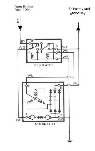
I think that this is the one you're looking for.
VR - ALT wiring diagram 79 and later.JPG

Note: There are 2 White/Blue (W/L) wires. Don't mix them up!
The thin one is between the N terminals.
The thick one is between the B terminals and continues to the fusible link(s) at the battery.

Rudi
VR - ALT wiring diagram 79 and later.JPG
 

Users who are viewing this thread

Back
Top Bottom