The Mean Green Bean's OBA thread competed, with numbers. (1 Viewer)

This site may earn a commission from merchant affiliate
links, including eBay, Amazon, Skimlinks, and others.

Joined
Jul 17, 2018
Threads
87
Messages
2,145
Location
LUGOFF, SC
I'm going to do a dedicated OBA thread for the MGB.
I've been futzing about with this since June, still waiting on some back ordered parts, so the urgency hasn't been what anyone would call "on point".
That said, I worked on mounting the air tank today.

I chose a seamless aluminum tank, 2.5 gallons in size. It fits perfectly in the cavity under the drivers side formed by the sliders, frame and arc under the seat. Its small enough to tuck up high and guarded.
1631387315760.png


I decided the best way to hold it there was a set of custom brackets that mount in 8mm Rivnuts on the frame.

One of the holes (bottom right) was kindly put in by Mr. T.
AupCjZMm.jpg


Here are the brackets, getting a coat of paint. The bottom hole and middle hole hold the braket to the truck frame. The top hole and the stud hold the tank brackets shown above.

CsTcQuRm.jpg

ZTLXXPom.jpg

The studs are made from hex head bolts. The heads were turned down to the min thread diameter and inserted into a hole from the front of the plate and plug welded from the back.
 
Last edited:
There is only one hole in the tank that is in the outer surface. Orienting this hole down to be a drain is a hard no, as the fitting would be unguarded.
So its going to be oriented toward the top and used as the input.
The two holes in the ends are the outputs, one to the front and one to the rear.
With no holes that can be gravity fed for a drain a touch of improvising is called for. Obviously an air compressor needs a drain so I created a flexible drain tube from 1/4" clear vinyl.
AKjcGEZm.jpg

The end is weighted with a pair of stainless nuts threaded over a brass ferrel so that no matter how the assembly threads into the tank the flexible tube will always be at the bottom and air pressure will blow the condensation out.
The tank end is a bit more complicated.
7GkV3CSm.jpg

On the left is a 3/8" to 1/4" NPT adapter. I need it to act like a bulk head fitting with out being able to access the back side. To accomplish this the back side of the fitting is also threaded 1/4 NPT.
In the middle is modified 1/4NPT to 1/8NPT adapter. It has to fit through the 3/8NPT hole in the tank so after it was torqued to the improvised bulkhead fitting the hex was turned off in the lathe. The right fitting is an 1/8 NPT with a 1/4" hose barb.
And the whole assembly threads into the tank.
9Biz2PTm.jpg

qRVpMQdm.jpg

I ran out of thread tape, that' why its not put together.
The fitting in the front is taped and hand assembled but not torqued in yet.
The drain will be routed to the front of the rig so the tank can be drained conveniently after use via a ball valve.
The front fitting goes to this quick connect chuck that will be mounted on top of the passenger side frame horn behind the bumper.
wQfKrmVm.jpg
 
Last edited:
Figured I'd pick this up where I ran out of daylight for pics last night...
So that QD hose fitting mounts with a standard bumper bolt, right up front.
x3Lkkg8m.jpg

9Wt20vom.jpg

The air hose hose snakes through one of the vents in the bumper.
tyJBLzdm.jpg


Air Brake Tubing with push-to-connect fittings will be used throughout the rig to convey air.
XVAwnJsm.jpg

For those than haven't played with these, they are dead simple fittings, just shove the tubing in till it bottoms. That's it. If you need to remove the tubing, depress the lock ring (green on this part) and pull the tube back out.
m3MH2nZm.jpg

eoErQWBm.jpg

Trail repairs are super simple, carry a length of tubing and a couple unions and you can cut out a busted section, splice in the repair and have pneumatics back up and running.
 
Last edited:
I know what you're wondering, "where is all this air going to come from?"
This beast!
JEzw3Mfm.jpg

It's a modified York 210 mounted to Joey's (Witt's End) OBA bracket.


Quoted from Off road Only
"This new york air compressor contains pistons with an oil control ring, steel cylinder sleeves, improved airflow inside the head chamber to allow for less oil intrusion and a finned head allowing for extra cooling.


This is a 10 cfm compressor, meaning at 1000 rpm it will deliver approximately 10 cfm of volume. The back bearing plate is modified to utilize an installed sight glass. When mounted vertically, the proper oil level (10 ounces) will result in a level shown in the middle of the window."

After reading everything I could get my hands on about York compressors this looked like the right path.
And it fits perfectly... but not without a false start.
The suction side has to stay pointed "back". I rotated it 90 degrees to the left at first so I could use a straight fitting and point the suction line toward the air cleaner, and in the driveway everything was fine. But when I was in reverse pushing a trailer up over a mound and had a fair bit of torque on the drive train the engine rose up and the AN fitting rubbed the PS battery box surround under the hood. Startled me pretty good.
4ls1Ggom.jpg

19wix94m.jpg

So that's why it has the 90 degree AN fitting coming into the suction side.

The blue hose and fittings are from Pegasus Racing.
This is the hose:
RIXq7TAm.jpg
eepWsifm.jpg
oyoenBZm.jpg


On the suction side, you just shove the hose over the barbs on the AN fitting and that's all that's needed.
On the pressure side though, a Oetiker double ear clamp ring is required.
l44BxBjm.jpg

4Qz6ABVm.jpg

meUW8tTm.jpg
 
Last edited:
Being the cheap, errr thrifty, guy I am, I modified a set of garage-sale-find lock jaw pliers with a rat tail file to make the crimp.
9XuiMMim.jpg


And that's where it all sits today. Nothing is actually mounted to the truck except the York. I don't want open air fittings getting crudded up while I'm waiting for the back ordered parts. But everything is prepped and ready.
 
Last edited:
TBD
 
Impressive sir!
 
Looking good! Where did you get that brass bulkhead fitting that the chuck mounts to?
 
So how many bananas job is this?
I'm not sure, so far it's required:
Modified/custom made tools: Locking Jaw Pliers, rivnut holding plate, stubby 7/16" twist drill (cut off and resharpened),
Power Tools: 90 degree angle drill, milling machine (used as a drill press), engine lathe, wire feed welder, Port-a-Band, hand drill, angle grinder, bench grinder.
Hand tools: hack saw, files, wrenches and assorted punches and hammers.

Obviously bananas can't be figured by addition or multiplication, just too many 'nanners. So it must be on a Logarithmic Scale or some other power.
Square roots seem to work. Add up all the various tools used and take the square root. sqrt(16) is 4
And that seems reasonable: :banana::banana::banana::banana:
 
Last edited:
Update time!
I have a Wheeling trip coming up in June and the rig "needs" lockers. Or at least that's what I'm telling the wife.
And since I'm "in there", the stock 4:11 gears are getting updated to 4:88. to better handle the trailer and bigger tires and low range control.
And because the Mean Green Bean is going to have OBA, might as well run air lockers.
I wanted TJMs, can't get them till August. Nitro Gears sells the gear kit with ARB lockers as a package deal, so that's the pile of parts sitting on the fireplace hearth in the living room.

The OBA must be completed!

I gave up waiting on the back ordered parts and took off on my own to figure out the manifolds, brackets and what-nots for both the ARB's and OBA.

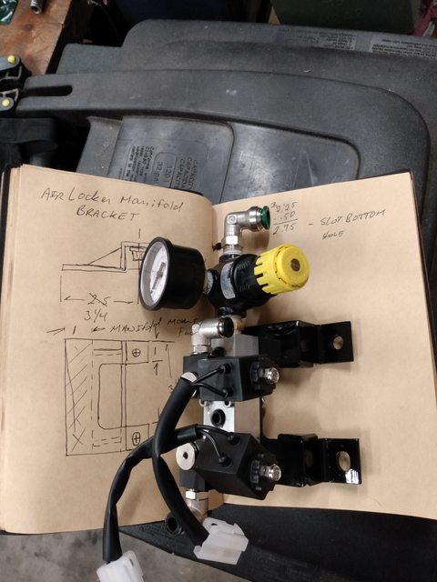
Here is the manifold system for the ARBs.
nx5bvdul.jpg

tEg8E9zl.jpg


Inlet is at the top with 3/8" DOT air brake line. Into a regulator, then into the manifold with the ARB solenoids and their 6mm air line fittings.
The ARB's need a regulator to get 60-75 95-105psi function pressure down from my unregulated 150psi system pressure.
It mounts to the fire wall where the front brake line and the diagnostic port are held to a pair of weld nuts.
75ATufZl.jpg


The brake line holder thingy got rotated 90degrees up and the Diagnostic box got relocated to one of the evaporator bolts.

The top 6mm airline is for the rear locker and will track back across the firewall and down the left side of the rig, to keep it away from exhaust heat.
The bottom ARB fitting points right down the front brake hard line, so I will follow that down and over to the pumpkin for the front locker.

Main OBA manifold....WHAT A PAIN IN THE DICK this was to figure out! I must have stared at the truck for 6 hours, moving stuff around, using blocks of wood to find the dead zones and generally trying to figure out where to mount the bugger. I gave up on making it look like the unit I wanted and just rolled with what's available.

I welded up bracket that uses the Cruise Control mounting bolts to hold the air manifold/relay and switch over the top of the CC mechanism.
qynjEPTl.jpg
 
Last edited:
I haven't decided yet if it needs a third leg that goes down to the third mounting bolt for the CC, right next to the air box mount on the inside of the fender...I'll get a better feel for rigidity after the whole kit's installed.

The OBA manifold mounts on top of the bracket, the relay for the York compressor clutch mounts via the rear bolt and hangs under the bracket. The switch is a lighted unit that when "on" and the compressor is not running, glows red. Its an extra I had laying around from the bumper light project.
rfQqYzZl.jpg

m0wlIcvl.jpg


Here is the inlet hose layout:
suction line attached to the air cleaner.
Outlet line through a 180 AN8 fitting and around the right side and across the front of the compressor to Witts Ends collessing filter mounted to the air box.
From the collessing filter out to the OBA manifold, where it enters a check valve. In the manifold is the pressure switch, (ARB 120psi on/150psi off), The emergency blow off valve (175psi) and a 0 to 200 psi gage.
TXTKJBFl.jpg
 
Last edited:
Couple of things to note if you decide to go this route.
The OBA manifold is a McMaster Carr part, 1/2NPT in both ends and 6 1/4 NPT outlets on one side.
The 1/2 NPT check valve threads right in, but has zero radial clearance for air flow. Its designed to be threaded into a tank through a welded bung, not shoved into a manifold. You're going to need a lathe to bore out a space beyond the threads and around the check valve body so air can flow in. I don't have a pic, but trust me, if you go this route, you'll see what I mean.
It could be done with a mill too, but I used the lathe because I have better boring bars for that.

You're going to need a welder for the various brackets, I guess you could bolt them together, but a little wire feed unit is the nuts for this. Th OBA bracket is a piece of 2 x 2 angle with the mounting leg cut down to 1 1/4 and drilled to clear the CC mounting bolts. Then a piece of 3" flat plate welded on the underside of the 2" leg for the manifold support. There's probably a better way but the 8mm bolts holding the CC mech to the fender are pretty rugged and were really attractive for holding the bracket. But its back where the hood strut lives so it has to be spaced out a good 1 1/2" from the inside edge. The 2" leg over the mounting plate provides a natural spacer keeping the manifold out of the hood strut's resting position.
repost of the bracket pic for reference:

qynjEPTl.jpg
 
Last edited:
I haven't decided yet if it needs a third leg that goes down to the third mounting bolt for the CC, right next to the air box mount on the inside of the fender...I'll get a better feel for rigidity after the whole kit's installed.

The OBA manifold mounts on top of the bracket, the relay for the York compressor clutch mounts via the rear bolt and hangs under the bracket. The switch is a lighted unit that when "on" and the compressor is not running, glows red. Its an extra I had laying around from the bumper light project.
rfQqYzZl.jpg

m0wlIcvl.jpg


Here is the inlet hose layout:
suction line attached to the air cleaner.
Outlet line through a 180 AN8 fitting and around the right side and across the front of the compressor to Witts Ends collessing filter mounted to the air box.
From the collessing filter out to the OBA manifold, where it enters a check valve. In the manifold is the pressure switch, (ARB 120psi on/150psi off), The emergency blow off valve (175psi) and a 0 to 200 psi gage.
TXTKJBFl.jpg
Looks great
 
I have wire harness parts coming this week to button up the wiring for running the lockers off the Locker ECU plug in the right side foot well and some more push-to-connect fittings for the pneumatic circuit in the truck.
Once that's wrapped up...Time for Gears and Lockers.:smokin:
 
In my best Si-Fi fake computer voice <Pneumatics Complete>.

The tank is tucked up tight between the frame and sliders.
The rear plug will one day be turned into an outlet for an air chuck at the rear of the rig... or train horns.
wEe7BOcl.jpg

jqQD9Mpl.jpg


Here's the air lines under the hood. The ARB manifold has the regulator set to 95PSI and the lockers are working well.
Uabh3IMl.jpg


And finally the air chuck and tank drain behind the front bumper.
I need a piece of neoprene or something similar to put around the shank of the pacifier to keep the air chuck clean.
The ball valve controls the tank drain, its exit line goes out toward the rear of the bumper next to the left side frame horn.
I am tempted to run it into the motor housing around the winch for an air cooling system. The RPMs will be up for winching anyway, so it should produce plenty of air for forced cooling of the motor.
ZEmaLiSl.jpg


If anybody needs additional pics or hints and tips, just ask.
Took me almost a full year between ordering the initial parts and getting it finalized.
Glad I finally have it completed.
I'll run some tests for filling times and CFM results with actual numbers, but for now... it fills tires fast, much quicker than my Bosch pancake compressor.
 
Nice work!!! Are you going to install a skid plate on the sliders to protect that bad boy? Prob not necessary but would be a easy fab job with your skills!
 
I have given a skid plate some thought, but the tank is so far up in that pocket I think its probably OK. I'm more worried about branches snagging an air line. Might do a grating type brush deflector.
 
Numbers!
According to the math and assuming the tank really is 2.5 gallons plus 50ft of 3/8" air line. (I've never actually measured the tank, just going by the literature.)
The system is putting out ~6 CFM at 1200 RPM. I'm not gonna lie, that's a touch disappointing from the advertised 10CFM at 1000 RPM. But there's going to be some line loss and I'm not measuring it directly off the compressor and excuses excuses....

As for practical application: Filling tires is quick! 16 to 38 PSI in 45 seconds on my 33's. The compressor pumps at a constant 118-ish psi (the needle is bouncing).
Which sure beats the pants off my pancake compressor in the shop, that makes me stop filling the tire and wait for it to top off.

Overall, I'm please with it.
 

Users who are viewing this thread

Back
Top Bottom