
This thread is the result of many hours of research and questions asked. I am using it to compile the final data for how to desmog a 79-80 FJ40 while still retaining beneficial systems. This is not intended to be a debate on the merits of desmogging your vehicle, those discussions exist elsewhere.
That being said, if any of the following looks inaccurate let me know and I will edit.
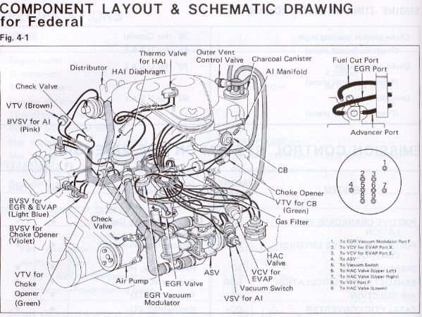
The following diagrams show the stock emissions system
 79emission%20schematic
79emission%20schematic2
By desmogging we eliminate the following systems:
Air Injection (AI)
Exhaust gas recirculation (EGR)
Choke Opener (CO)
And we retain the following systems:
distributor advance
deceleration fuel cutoff (i.e. vac switch, fuel cutoff solenoid)
evap (i.e. fuel tank and carb bowl venting, charcoal canister)
choke breaker (CB)
hot air intake (HAI)
distributor cap vent
hot idle compensation (HIC)
positive crankcase ventilation (PCV)
-optional- High Altitude Control (HAC)
The following schematic shows the overall result w/o HAC, w/ HAC will be discussed later.
79emissionschematic - for Desmog - w-o HAC
The following posts will outline these systems individually.
That being said, if any of the following looks inaccurate let me know and I will edit.
The following diagrams show the stock emissions system
 79emission%20schematic
 79emission%20schematic2
By desmogging we eliminate the following systems:
Air Injection (AI)
Exhaust gas recirculation (EGR)
Choke Opener (CO)
And we retain the following systems:
distributor advance
deceleration fuel cutoff (i.e. vac switch, fuel cutoff solenoid)
evap (i.e. fuel tank and carb bowl venting, charcoal canister)
choke breaker (CB)
hot air intake (HAI)
distributor cap vent
hot idle compensation (HIC)
positive crankcase ventilation (PCV)
-optional- High Altitude Control (HAC)
The following schematic shows the overall result w/o HAC, w/ HAC will be discussed later.
 79emissionschematic - for Desmog - w-o HAC
The following posts will outline these systems individually.
Last edited:
 IMG_0794[1]
 79emissionschematic - Choke Opener
 IMG_0799[1]
 IMG_0800[1]
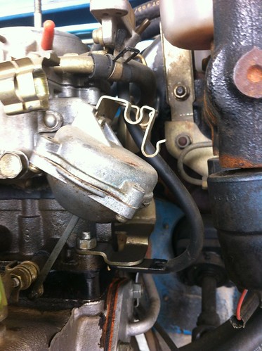
 Removal of CO
 IMG_0844
 Removal of CO Linkage
 IMG_0842
 IMG_0843
 IMG_0845
 79emissionschematic - Advancer
 IMG_0783[1]
 IMG_0782[1]
 79emissionschematic - Vac Switch2
 IMG_0806[1]
 IMG_0787[1]
 IMG_0786[1]
 79emissionschematic - Evap
 IMG_0784[1]
 IMG_0788[1]
 IMG_0789[1]
 IMG_0817[1]
 IMG_0792[1]
 IMG_0791[1]
 IMG_0790[1]
 IMG_0770[1]
 IMG_0793[1]
 79emissionschematic - Ported CB HAI & Dist Vent
 IMG_0798[1]
 IMG_0772[1]
 IMG_0771[1]
 IMG_0773[1]
 IMG_0774[1]
 IMG_0775[1]
 VCVdetail-1
 IMG_0780[1]
 IMG_0778[1]
 79emissionschematic - HIC
 IMG_0767[1]
 79emissionschematic - for Desmog - w HAC
 79emissionschematic - HAC
 IMG_0825[1]
 IMG_0827[1]
 IMG_0828[1]


