"The Big Three" Electrical Upgrade (2 Viewers)

This site may earn a commission from merchant affiliate
links, including eBay, Amazon, Skimlinks, and others.

Joined
Jan 4, 2014
Threads
94
Messages
3,024
Location
Little Rock, Arkansas
Website
www.facebook.com
You might have recently seen in the photos thread that I upgraded my engine-ground wires. No I don't have an upgraded alternator at the moment but plans for one are in the near future so that is partly why I decided to do this mod now. I went with 1/0 pre-tinned copper lug terminals from Little Rock Bolt & Supply Co. and 1/0 tinned OFC copper ground wire that I found at Home Depot. First step was taking pieces of string to measure the different lengths of wire that you will need. I came out with
  • Engine-Chassis: 2'3" and 1'
  • Battery-Chassis: 7.5"
I found the best way to secure the wires in the lug terminals was to clamp the terminals upside down in a vice and cut little pieces of solder in the wire cavity. I used a Map/Pro Bernzomatic torch to heat the terminal by holding the flame right at the base of the crimp. As soon as the pieces began melting I fed long strips of solder into the cavity until it was about half full. I then started heating the wire so that the solder could bond securely and this took a bit longer than the terminals. I slowly inserted the wires into the lugs stopping about halfway to let it flow between the wires. Then I just pressed the wire in has hard as I could and killed the torch. Slid marine grade heat shrink over it and I thought they turned out pretty good:

IMG_7887fav.jpg


I found two ground wires for the engine but if anyone knows of more please let me know. One between the heater tee's:

IMG_7852.jpg

And another one that goes from a bolt on the side of the engine to an area next to the main fuse box and dip stick under the hood. I didn't get a pic of it originally but here is one with the new addition:

IMG_7890.jpg


Both:
IMG_7902 (1).jpg


Notice I said addition. I did not replace the factory ones, I simply added on to them. I took a small wire wheel on the end of my power drill and got all the dirt and grime off the grounding surfaces. I then used 220 grit sandpaper to clean up the factory ring terminals which really weren't bad to begin with. I have heard this could potentially benefit more by keeping both grounds...? Not 100% sure on that so please correct me if I'm wrong, just something I've heard. I will post more pics tomorrow of the battey-ground wire. It started raining as I was finishing that install so I didn't get any. It ended up being a little trickier that I thought. Pre-upgrade: 14.2V Post-upgrade: 14.66V

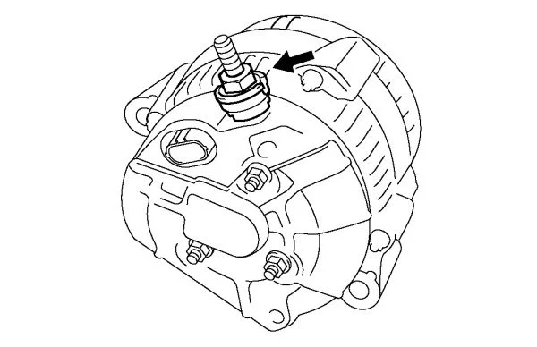
My next objective is to upgrade the alternator-power wire. Due to the location of the alternator this is going to be a much bigger challenge. The power wire connects to the alternator by what I believe is a connector on the backside. I removed my skid plate to see if I could get at it from the bottom but no luck. So now I have two questions: 1) Has anyone else done this and have experience with upgrading the alternator wiring without actually removing the alternator, 2) How could I attach the appropriate connector to the 1/0 cable (and where can I find it)?
 
Last edited:
Haven't actually messed with the alternator other than what little I did to change the timing belt and water pump. That said, the factory service manual and the electrical wiring diagrams book both show the main power lead off the alternator as a ring terminal at top rear. There is also a three wire plug near it that has a wire running to the 7.5A fuse in the fusible link box. I'm guessing you would only tackle the larger main wire that has a ring terminal. Hope this helps - maybe find it by touch and see if you can avoid all the work the FSM says is needed to remove, i.e., R&R radiator and PS pump.

full
 
My memory is fuzzy but you might be able to access the charge cable after removing part of the inner fender liner.
 
Haven't actually messed with the alternator other than what little I did to change the timing belt and water pump. That said, the factory service manual and the electrical wiring diagrams book both show the main power lead off the alternator as a ring terminal at top rear. There is also a three wire plug near it that has a wire running to the 7.5A fuse in the fusible link box. I'm guessing you would only tackle the larger main wire that has a ring terminal. Hope this helps - maybe find it by touch and see if you can avoid all the work the FSM says is needed to remove, i.e., R&R radiator and PS pump.

full
Thank you for that diagram! I must've been feeling the wrong wire then. The fusible link coming off of the positive terminal of the battery looks to have 2 wires going into it. I may be wrong but I swear that is what it looked like when I took a peek yesterday. I'm guessing both the larger power wire and the three-wire plug both go to that fuse..?? I really couldn't get a good look at it even with the skid plate removed but I'll follow @hoser advice and pull the inner fender liner tomorrow and see if that makes it more easily accessible. @Bretthn yeah I dont plan on removing it just for the wire upgrade. I'd rather wait until it needs to be replaced and maybe put a sequoia alternator in its place along with a 1/0 power wire.
 
Thanks for the info. I'm thinking about doing the grounds also since I'm in the middle of a dual battery install. Question: Any reason why you decided to double up the grounds rather than just removing the stock grounds and replacing with the 1/0?
 
^ interested in the same question.

Also @TheForger, you keep doing mods that are on my list and I'll just follow your instructions, ok?
 
...The fusible link coming off of the positive terminal of the battery looks to have 2 wires going into it. I may be wrong but I swear that is what it looked like when I took a peek yesterday. I'm guessing both the larger power wire and the three-wire plug both go to that fuse..?? ...

Correct per wiring diagram. Not near my truck now to verify, but the fusible links shown on the diagram for a 2000 LX have two lines in from the alternator (one at 140A and one at 7.5A).
 
I may have missed it, but what is the reason for this modification? Is there an issue with the factory grounds?
 
Last edited:
I may have missed it, but what is the reason for this modification? Is there an issue with the factory grounds?

I haven't heard of any issues with this specific vehicle like with others. The purpose of improving grounds is to ease the flow of current. In many vehicles this results in a smoother idle and less issue with flickering headlights when adding electrical loads.

Some cars like the GC chassis Subaru Impreza have a very noticeable change after improving the grounds.
 
I may have missed it, but what is the reason for this modification?

Back in the olden days it was a car stereo competition thing.

They used to have competition classes based on the advertised wattage of the amplifiers. So of course the manufacturers made what were informally known as cheaper amps - amps that had loosely regulated power sections that responded with significant power increases if the rails were given any additional voltage to work with.

As an example, I have an old 2-channel Pioneer Premier amp in the closet that was rated at an advertised 50 Watts per channel at 12 Volts with 0.08% THD across the whole 20-20KHz spectrum. Since the power section of the amps is loosely regulated it responds well to increases in supply voltage - my Premier amp was certified at 238 Watts per channel at 14.4V.

So the chase was on by car owners to minimize voltage drops from the alternator/battery to car audio components.

Then around the early 1990s (back when I had a second gen Toyota MR2) there was a argument being waged about increased voltage and its effect on the spark plug arc/engine power production. There used to be all sorts of JDM kits that upgraded the wiring harnesses.

Fast forward to today and I then defer to folks such as the post from @ihadmail above.
Great summary, exactly describes the reasoning for this mod as well as simple peace-of-mind. @sdnative I did notice a 0.46v increase at the battery after doing just the battery-chassis and engine-chassis grounds. Not sure if it's due to this mod or if it is a coincidence but it was there. Both environments were the same - cold engine, garaged, etc...and the measurements were taken only an hour or so after one another.

^ interested in the same question.

Also @TheForger, you keep doing mods that are on my list and I'll just follow your instructions, ok?
Sounds good to me, seems like it works both ways:)

I may have missed it, but what is the reason for this modification? Is there an issue with the factory grounds?
No issue but I do have a 500w amp powering a subwoofer, a 50w x 4 channel powering door speakers, light bars/pods, HID's, CB radio, and a winch. I have found myself running all of those at the same time and there's no doubt that puts a large strain on my battery and alternator. Upgrading to a larger diameter wire causes less resistance and allows electrons to flow more smoothly as stated by @ihadmail

Thanks for the info. I'm thinking about doing the grounds also since I'm in the middle of a dual battery install. Question: Any reason why you decided to double up the grounds rather than just removing the stock grounds and replacing with the 1/0?
Well I did a lot of research on this question and found that there really isn't a right or wrong way to go here. Popular websites (Crutchfield, SonicElectronix, etc...) as well as a few Youtube videos I watched stated that you can either "replace or augment existing ground wires". The only real reason I have found for a complete replacement of the factory grounds is if the cables were heavily corroded or damaged in any way that could limit current flow or increase resistance. Mine were in pretty good shape so I figured it came that way from the factory and worked so it made sense to leave them in place. It would be just my luck that I would remove & replace a simple ground wire and for some reason my truck won't start...
 
One more question: What would be the best way to go out attaching the 1/0 lug terminal to the fuse block? Those terminals are pretty large and after looking at the block I wasn't sure if it would fit. Didn't have the terminal in hand though so not sure but that could be a problem...I guess I could file down the edges of it
 
I would offer a word of caution on your method of attaching the lugs. Solder is really not an ideal bonding agent, especially for high vibration environments. Solder can be brittle, and over time it can also work harden the wire causing it to break. The preferred method is to crimp the lugs. I have had good success using one of the fairly inexpensive hydraulic crimpers from Amazon (~ $45). Not to say that soldering won't work, just informing of a better method.
 
I would offer a word of caution on your method of attaching the lugs. Solder is really not an ideal bonding agent, especially for high vibration environments. Solder can be brittle, and over time it can also work harden the wire causing it to break. The preferred method is to crimp the lugs. I have had good success using one of the fairly inexpensive hydraulic crimpers from Amazon (~ $45). Not to say that soldering won't work, just informing of a better method.

I agree, crimp all the way. If your hydraulic crimper is yellow and comes in a yellow box (like the harbor freight one from China), I have the same one and it works great. You can find them on ebay now for less than $40 shipped. All my wires are crimped/heat shrunk at the terminals and protected with braided wire loom.
I actually considered doing both but I did not have a hydraulic crimper and did not plan on buying one to only use it for this application (I don't know when I will ever crimp 1/0 wire again). The thing is crimping also has its con's and can work harden wire just as easily. Crimps are the weakest part of a wire, just like how a knot is the weakest part of a length of rope. Sure soldering may not be the best method, but I can guarantee these will never come apart. You really can't go wrong with either method, but preferably you would want to crimp and then solder and heat shrink.
 
I actually considered doing both but I did not have a hydraulic crimper and did not plan on buying one to only use it for this application (I don't know when I will ever crimp 1/0 wire again). The thing is crimping also has its con's and can work harden wire just as easily. Crimps are the weakest part of a wire, just like how a knot is the weakest part of a length of rope. Sure soldering may not be the best method, but I can guarantee these will never come apart. You really can't go wrong with either method, but preferably you would want to crimp and then solder and heat shrink.

The $32 (with free shipping) hydraulic crimper I got came with dies for 8 different gauges of wire. It does more than just 1/0. For me, it was worth adding it to my tool box considering all of the crimping I've done on many, many projects and all of my future projects.

Also, since it seems you agree with the factory ground wire design, aren't all the factory grounds crimped? Just food for thought.
 
I would offer a word of caution on your method of attaching the lugs. Solder is really not an ideal bonding agent, especially for high vibration environments. Solder can be brittle, and over time it can also work harden the wire causing it to break. The preferred method is to crimp the lugs. I have had good success using one of the fairly inexpensive hydraulic crimpers from Amazon (~ $45). Not to say that soldering won't work, just informing of a better method.
Solder is not used for lugs in aircraft, nor in military ground vehicles...and I try to follow both standards when I add or modify wiring.

Wires soldered to lugs may have issues with vibration eventually causing broken cables...the break location is typically at the point where solder wicked down the wire away from the crimp barrel. If you find you need to bend the cable a bit after soldering you'll find it's a PITA, especially on larger cable gauges.


I actually considered doing both but I did not have a hydraulic crimper and did not plan on buying one to only use it for this application (I don't know when I will ever crimp 1/0 wire again). The thing is crimping also has its con's and can work harden wire just as easily. Crimps are the weakest part of a wire, just like how a knot is the weakest part of a length of rope. Sure soldering may not be the best method, but I can guarantee these will never come apart. You really can't go wrong with either method, but preferably you would want to crimp and then solder and heat shrink.
No disagreement that a continuous wire is better than one with a crimp.

Crimp lugs and splices are, if you do not buy auto store crap, normally 1/4-hard copper. Cable conductor is normally annealed. Using a good crimp with the proper tool makes "work hardening" impossible. In testing, normally a crimped connection has better pull-apart strength than a soldered joint.

Not sure why you'd want to solder, assuming you have a good crimp splice. ;)
 
@reznut I may add one to my tool shelf later on down the road. Another reason I chose solder is for aesthetic reasons. Yes hate all you want but my OCD will not allow for ugly wiring. And IMHO crimps aren't the most attractive thing while a soldering job with heat shrink over it is nice, clean, and semi-professional looking.

But yes all of the factory grounds are crimped. And every one one of them had exposed wiring at those crimps since they were unprotected. This wire had discolored and a tiny bit of surface rust began to form on the wire. Nothing a wire wheel couldn't take care of but the fact is they were crimped and not wrapped in any protective sheathing to prevent exposed wire.

The difference between soldering and crimping, when done properly, is so small it's not even worth debating. The method you choose isn't as critical as the technique
 

Users who are viewing this thread

Back
Top Bottom