Phoenix gets a new set of underwear (driveline upgrades to my FJ40) (1 Viewer)

This site may earn a commission from merchant affiliate
links, including eBay, Amazon, Skimlinks, and others.

are you using a crush sleeve or solid spacer on pinion?
after reviewing the pic saw the crush sleeve. same goes of it as the carrier nuts . better get ya a young-un wit lots of muskles as popeye would say:)
It is a solid sleeve, Paul. I guess it looks like a crush sleeve. I don't know how they look because the OEM pinion uses a shoulder on the gear that acts like a solid sleeve. I have measured (kinda) the depth (taking into account differences in bearing design and other factors, like Spock) and I am starting with one shim beneath it. It came with quite a few mostly about the same thickness.
 
I heated the outer (front) pinion bearing to 350 F today. It slipped on the assembled pinion/diff after some taps with a punch...the Nitro pinion has a shoulder that makes positioning the bearing difficult whereas the OEM pinion was tapered...and tightened the nut with a ratchet but not tight. No preload and some play, so I will remove the pinion with the press tomorrow and add a shim.

pos-3.JPG
 
Today was school day! First, the heating method is inconsistent and cannot be relied upon as well as being really slow. The outer bearing is easily installed by the press with a short 4x4 piece supporting the pinion and the same arbor as used for the inner bearing...more reliable and much faster, despite setting up the press for install/removal operations. This Nitro pinion has extremely small tolerances and there is no play for the outer bearing.

The second lesson involves the simple instruction in the Nitro install guide, "Install pinion & tighten nut until there is no slop and a bit of preload". This is a painstaking operation. Slop is eliminated by just installing the oil slinger, pinion flange, washer, and the old nut. Preload and no slop involves the set of shims that came with the Nitro solid spacer. The shims are not color coded, labeled, or even differentiable without measuring each one's thickness. The shims have to be added beneath the spacer to exactly push against the outer bearing inner cage so as not to push the roller bearings away from the bearing race, and I mean EXACTLY. I installed and removed the outer bearing five times today and learned this lesson. At this point I realized that Nitro knows better than to supply a bunch of same-thickness shims for a detailed operation, and I got out my 35 year-old micrometer (0.001 inch accuracy). The shims are metric and the accuracy of my micrometer is (apparently) limited. I measured each shim at 4-8 points twice and came up with the simple numbering scheme seen in the photo. Number 1 is the thinnest and 8 is the thickest. Ten-thousandths of an inch are estimates only.

Tomorrow, I will assemble the pinion with number 5 because I had no slop with one of the ~0.02 inch shims (my original measurements?!). If it has slop I will remove the bearing and reassemble with number 4, which should decrease slop because it is thinner. If it has no slop but no preload, I will go to number 6. After a few iterations, this should work...if it doesn't I will be calling a Nitro distributor for more shims!

labeled_shims.jpg
 
Last edited:
are we keeping track of the hours spent ?
 
Just shy of a few, not quite a bushel.
I only work on this about 1 hr per day. However, I have a technical question for Paul or anyone who can answer: what is the proper spanner for the original carrier bearing adjuster? It looks like ~2.5 inches. I will need to get the ARB spanner from them because the cap on the right? side was out of alignment at the factory and the ARB adjuster has sharp threads that hang up when trying to engage the cap threads. The OEM adjuster has a much smoother finish and went on the left? side, which was also properly aligned when the bearing holes were drilled.

This introduces the day's work...the number 5 (~0.0202 inches) got the desired "bit of preload" and I have installed the locker in preparation to measure pinion depth. Now another work stoppage to acquire proper spanners because the OEM and ARB are completely different.

Here is the setup to set the backlash preparatory to checking pinion depth.

pinion_depth_setup.jpg
 
if those carried nuts arn`t free sumtin WRONG!
 
As I explained in the previous post, something was wrong at the Toyota factory that assembled them. However, they were drilled for the carrier bearing caps and bearings correctly; the issue (not really once I have the ARB tool) is that the adjustment nut threads thru the differential housing threads and then hits open air for ~1/2 inch before contacting the matching threads on the cap. The OEM adjuster was smooth because it has a better-machined thread pattern, so I guess that is wrong too...LOL! It does look a little curious, however, with the cap offset by ~1/8 inch.

Today I am waiting for the ARB "universal" adjuster nut pliars. I cleared space on the bench and disassembled the rotor/hub assemblies for the disc-brakes. It looks like someone actually had these apart and thought it was OKAY to reassemble with two missing (not broken...not there) wheel studs and one rotor-attachment bolt (again...not there)...it just gets better all the time in the words of Beetlejuice...

hub_sep.jpg new_hubs.jpg

The rotors look real good, so I will find someone to clean them up, after I have cleaned them up...don't want to freak out the shop! In order to get the bearings out, I think I need to remove the seal, but the "Knuckle rebuild kit" I ordered doesn't include these, although it does include the inner bearing...hmmmm. I will also replace all of the remaining wheel studs with new ones 1/4 inch longer to account for the wheel spacers, which I assume were necessary to clear the frame.
 
Last edited:
Today, I disassembled the hubs for the disc brakes, and found out why a couple of wheel studs and a rotor bolt were missing. One of the hubs looked like it had never been serviced, the grease had the texture of cold margarine, but the other (missing studs) was filled to capacity with fresh grease and shows evidence of a catastrophic wheel bearing failure. The damage is minor to the hub but a couple of the remaining studs were actually bent! One required a lot of pressure from the press and exploded like a bullet as it popped out, giving me quite a start!

It turns out the inner hub seal is in the rebuild "kit"; I just didn't recognize it until I saw the old ones. The press was critical for removing the studs, as shown in the attached photo.

stud_removal.jpg

I also have a couple of general inquiries that I would appreciate any input on: (1) should the diff bearings be coated with grease before final assembly?; (2) Are studs really necessary on the locking hub because the old drum brake hubs used bolts and these studs are kinda annoying to deal with, not to mention they were dinged up from general off-road use; and (3) does anyone have a number for the preload (lb-inch) for the carrier bearings? If I cannot find an answer I will just match (i.e. double total preload) what I get for the pinion preload...
 
Last edited:
I also discovered that OEM shims for the pinion preload "came" in ~0.001 inch increments, which Nitro did not supply with the solid pinion spacer...
 
Im not 100% on this but I'm pretty sure the diff bearing doesn't need grease because it should stay lubricated with the diff oil.

As far as the locking hub studs vs. bolts go, as long as the they are the same size and thread pitch, I don't see a reason why you couldn't use the bolts instead of the studs. They apparently worked fine on the older models.
 
The service manual answered all of my questions...lube with 90 wt on final assembly, set the carrier bearing preload to ~ 4 lb-inch, and the studs on the locking hub are OEM...FYI, something just arrived by FedEx but I will find out what manana...I am retired...LOL!
 
The package that arrived yesterday turned out to be the ARB carrier bearing pliars. I tried them out and easily (not much force) got the slightly mismatched bearing adjuster nut threads to turn smoothly. They also fit the OEM nut like they were made for them...very NICE! They are made of ~1/4 aluminum and very strong...these great tools make the job easy!
arb pliars.jpg
 
Today, I checked the pinion depth on the front diff. The first requirement is to get the backlash set by adjusting the adjuster nuts with the ARB pliars to get 0.006-0.010 inches of backlash. I couldn't get consistent results by zeroing the dial indicator so I started from a little more than 0.005 inches. These photos show the "precision" I got, i.e., the indicator returned to its starting point. It was set for ~ 0.009 inches.
2015-04-15 14.55.24.jpg 2015-04-15 14.55.27.jpg 2015-04-15 14.55.29.jpg

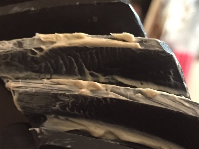
I used white lithium grease to mark the ring gears on opposite sides to compare to this image from the Nitro installation guide.

2015-04-15 15.16.23.jpg

The left images in the upper set are the drive side (convex) and the right images are the coast side of the gear (concave). The lower pairs of images are examples of patterns requiring increased pinion depth (more shims) on the left, and decreased pinion depth (thinner shim) on the right...continued in next post...

2015-04-15 15.12.31.jpg
 
Only five files can be uploaded, so I had to continue in this post. Here are my photos for the drive side:

2015-04-15 15.12.31.jpg 2015-04-15 15.15.36.jpg

Here are the coast side photos.

2015-04-15 15.12.31.jpg 2015-04-15 15.15.36.jpg 2015-04-15 15.12.47.jpg 2015-04-15 15.15.47.jpg

I am eliciting comments from viewers because nothing is ever as straightforward as in the instructions. I think it is okay but...
 
deep on drive but shallow on coast try to center it up but lean to deep drive
 
deep on drive but shallow on coast try to center it up but lean to deep on drive ps check BL at multi places should stay close to same at all points
 
deep on drive but shallow on coast try to center it up but lean to deep on drive ps check BL at multi places should stay close to same at all points

it is difficult to read the gear markings using the lithium because it sticks to the gears and gets smeared out somewhat; thus, I would call these results inconclusive, which is consistent with your interpretation (it doesn't help that Nitro has the wrong photo for the coast side pinion too deep). I have ordered the GM marker paint and when it arrives in a week or so, I will post new images and check BL at several locations.

The next post is going to explain some of the background info on using aftermarket gears to replace OEM gears, specifically with respect to the pinion depth and preload...
 

Users who are viewing this thread

Back
Top Bottom