Parasitic battery drain: Proper testing procedure? (1 Viewer)

This site may earn a commission from merchant affiliate
links, including eBay, Amazon, Skimlinks, and others.

CJF

Joined
May 31, 2005
Threads
49
Messages
7,238
Location
My work here is done.
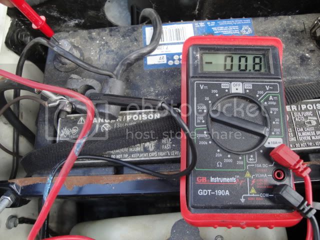
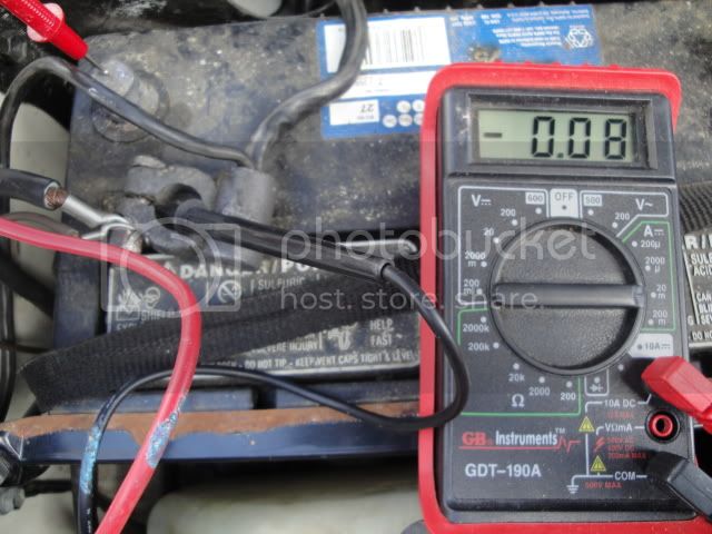
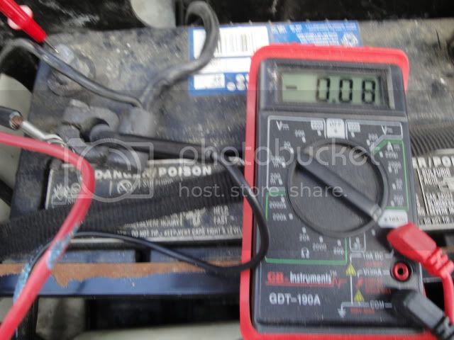
Seems like there have been a few threads recently in which parasitic drains (too much current with the vehicle off) came up. So what's the proper testing procedure? I've got a digital multimeter, but I'd sure love to have someone spell out step by step what I need to do so as not to blow myself up. :hillbilly:
 
well, you'd only have to put your multimeter in ammeter mode, disconnect the cables from the + terminal on the battery, bridge the gap with the multimeter and read. As long as the losses are less than the fuse rating in the multimeter, you won't blow it or yourself up.

then when you're done, don't forget (unlike me) to put the multimeter back in voltmeter mode so you won't blow up the multimeter fuse next time you use it to measure battery voltage (like me)... :)

Now, if it's a cheapo multimeter, it may not have a fuse but then the whole multimeter is the fuse, so it's the same idea.
 
What you need to do is get rid of everything aftermarket on it.

Damn stupid remote starter that PO installed....*grumbles*
 
It's pretty easy to localize right off the battery terminal. You have the feed to the starter and the feed to the fusible links in a stock config. The starter should be drawing 0.0mv.

You will need to separate the 3 links or simply open the black box and remove the 2 in there. Same principal applies. The DMM in series with the load being tested.

This way you can subdivide the main circuit drawing the most current. Once you know which main branch is drawing, you can continue to subdivide from there.

FWIW, mine draws 20-25mA at rest.
 
I have done the same as e9999 but instead of a multimeter I used a test light. A draw will usually light up the test light a little. Then I start pulling fuses till the light goes out then look into that circuit to find the draw.
 
keep in mind there will be some legitimate drain too. Like the clock for example. (and maybe some current into various memory devices?) so, get a feel for what the normal drain should be first, before taking things apart.
 
I have done the same as e9999 but instead of a multimeter I used a test light. A draw will usually light up the test light a little. Then I start pulling fuses till the light goes out then look into that circuit to find the draw.

A test light is a very good first step. If the bulb lights up you have a BIG draw and would probably blow the fuse in the meter.

Also, don't forget to wait a minute or two before taking your reading(s) because the system needs to initialize after being disconnected.

Rule of thumb is < 50mA is acceptable. >80mA and you should investigate.
 
I've always called 30mA the threshold between good and bad. The best way i've found to test is on the negative term. It ALL goes through that sucker.
 
Proof that I'm an electrical idiot:

What the heck is my meter trying to tell me here? :confused:

DSC00210.jpg


DSC00212.jpg
 
Proof that I'm an electrical idiot:

What the heck is my meter trying to tell me here? :confused:


Your meter is confirming you are an electrical idiot :)

You have your Red lead plugged into the 10A jack, it will ONLY display something valid if you also rotate the knob to choose the 10A setting.....

The "other" red jack is for all meter current ranges (and volts/ohms etc) below 10A.

The BEST way to measure current from something that can potentially eat your meter's amp range for lunch is a DC capable clamp meter....

cheers,
george.
 
what you want to do is start on the 10A setting, both where you "plug" it in and with the knob dial choice. (this is assuming you know/guess that it'll be less than 10A.) Then when you know what the draw is, roughly, if low enough you can move to the appropriate mA settings (matching both the plug and the knob). Right now you're on one of each, mixing things up as it were...
 
Move the red meter probe down to the mA jack on the meter and switch the dial to the mA scale. THs will give you a more accurate reading.
However this will just give you total draw. It won't tell you which circuit is drawing. You need to do this off of the positive terminal to separate the main circuits.
In any case 80mA is high if the truck is at rest. At least compared to my truck. However it is still a small load.
 
Yes, the meter is displaying 80mA and -ve because your leads need to be flipped.

Do note that meters (especially cheap junk) are very inaccurate when measuring low currents (like you are) on the 10A range. I suggest now that you know you don't have large currents that could blow the meter, to put the red lead into the mA (the other jack) and rotate the meter knob to the 200mA range to get a more accurate assessment of your quiescent current draw.

cheers,
george.
 
80mA draw will run your battery flat in about 3 weeks. 45000mAh/80ma/24h=23 days. This is the ragged edge of 'acceptable' draws.

Typical is about 30mA or less which will basically run a battery flat in 3x that, or 9 weeks (2 months)

Now that you know the draw is less than 1A you can switch the meter to the mA mode. Also, swap the meter leads around at the battery connection so that it's +mA readings so you're less confused.

The next step is to unplug the 3 fusible link wires one at a time, to narrow down the location of the draw. Also try unplugging the DOME fuse. Unplugging all the fuses one at a time (and re-plugging them) will show you the area which has the biggest draw.

Also, a quick shortcut (if it's simple) is to unplug all aftermarket accessories, including aftermarket stereos and amplifiers.

Basically split the circuits down one by one until you find the location of the big draw, around 50-60mA. Once you find the general location of the draw, you get to pinpoint it. That's the FUN part.

Keep us posted, we'll get you more hints as you go along

IMO the theory of pinpointing a parasitic draw is like a number guessing game we used to play as little kids. Guess a number between 1-100. You start with 50. And then find out that the number is >50 so guess 75. Half-way between the numbers, you'll narrow down the path until you find the exact spot.
 
Thanks guys! :)

I'll start following your instructions for pinpointing the problem and will be sure to post up as soon as I get stuck again. ;p

Curtis
 
Last edited:
Ok, so I have been working on this myself and now that I have a road map I went and got my meter and did the 10A/10A mode and it goes high initially but then settles in at about 0.06-0.07 read. So based on the above I then swap to the mA mode and turn it over to the 200 mA setting and I get nada.... So what am I doing wrong? Do I possibly need a better meter? I did both tests on the neg terminal. I did notice that in the 10/10 mode the lights did flash, which is what I figure gives me those first high readings, and I saw a spark when I close the circuit but not when I close it on the 200mA setting. My meter only has one mA setting and that is the 200mA, which is why I am wondering if I need a better meter.

I suspect a remote Start/keyless entry installed by the PO, but would be nice to know for sure.

Thanks for the good info.:cheers:

Tucker

Given you get sparks when you close the circuit, likely quite a high current spike and possibly large enough to have blown a fuse in the meter - assuming it has one - else it may have blown a component....

A technique to protect your low current ranges on a meter is to use clips to connect the meter leads to the battery post & battery cable - BUT leave one meter cable not plugged into the meter. Then connect battery cable to post to 'charge' up any initial current drawing devices (big capacitors etc), then plug in cable into meter and then remove the battery cable from the post. The meter will then measure the quiescent draw without having been subjected to the initial charging surge.

Finally, sparks when connecting leads to lead acid batteries (non-sealed units) can be potentially dangerous if there's a build up of hydrogen around the battery...

cheers,
george.
 

Users who are viewing this thread

Back
Top Bottom