FJ62 to 12HT - alternator connector (1 Viewer)

This site may earn a commission from merchant affiliate
links, including eBay, Amazon, Skimlinks, and others.

Joined
Feb 6, 2006
Threads
10
Messages
182
Location
Dripping Springs, Texas
Ugh! I am stuck and need some help. I have searched for several hours through the forum but can't locate an answer. But I know that many people have solved this and someone can quickly provide a direct answer.

Here is my situation: I have a 1989 US-version FJ62. Transplanted a 12HT into the truck. The mechanic that did the swap cut the truck-side three-prong connector to the alternator and just hooked up one wire to the alternor's three-prong connector (not talking about the alternator B terminal here). I would like to reconnect all three wires to the alternator. My alternator has an internal IC Regulator and is 12V.

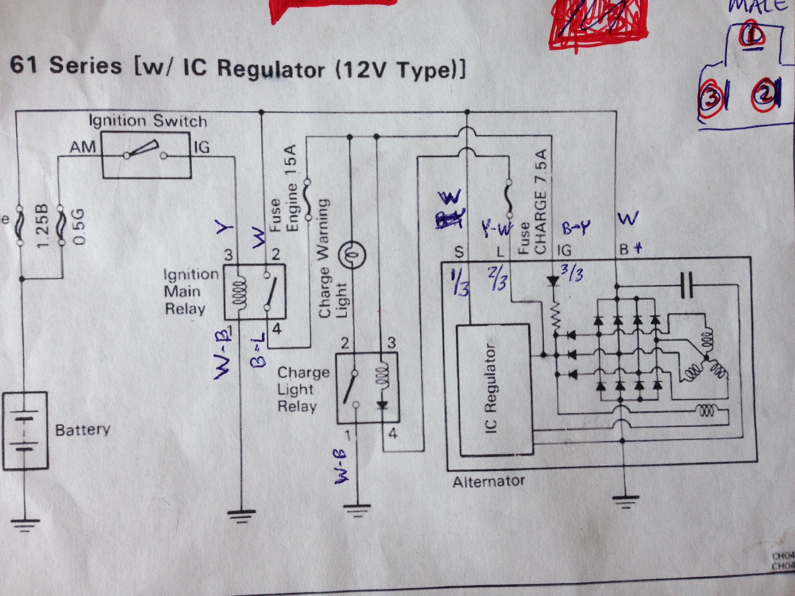
I am having a tough time determining which wires connect to which wires. I have attached pictures for reference. I would be very grateful if someone can tell me specifically which wires from the wiring harness connect to which of the alternator wires. Also, can someone tell me which of the three alternator wires (red, blue, white) correspond to S, L, and IG on the wiring diagram.

Pic #1: shows the internal IC Regulator and the three wires from the green connector (red, blue, white)

IMG_7510.JPG


Pic #2: Shows the backside of the green connector (red, blue, white wires)
IMG_7511.JPG


Pic #3: Shows the three wires from my wiring harness. Also, you can see that two of the wires (thicker white wire, medium sized yellow wire) have been cut. Also, you can see that the B-Y wire has a connector; this was the only single wire that was connected to the green alternator three-prong connector.
Can someone tell me the proper way to connect these three wires to the green connector?
IMG_7512.JPG


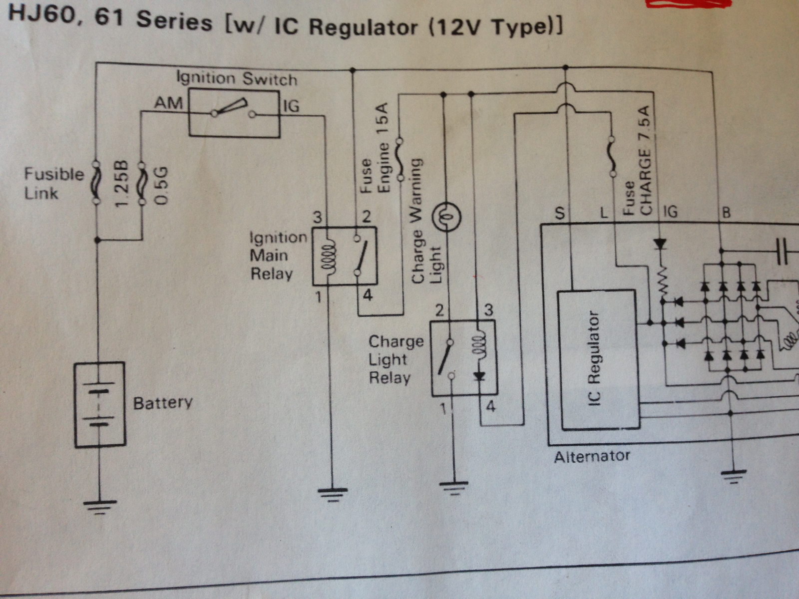
Pic #4: Diagram from the 12HT Repair Manual. Can someone tell me which wires in the alternator (red, blue, white) correspond to S, L, and IG?
IMG_7513.JPG


Thanks in advance!

-Sean
 
IMG-20160430-WA0007.jpg

The sticker. It shows the plug and tells you what is ignitioN, sense, and hot.

A.J
 
A.J.,

Thanks for the reply. However, that is not very helpful to me. If you know what is what, can you please just tell me instead of sending a picture and telling me to look at the picture. I don't understand that diagram.

Thanks,

Sean
 
I got it figured out.

Pic #1: Part of the wiring diagram from the FJ62 Repair Manual showing the alternator (w/ IC reg), the B, L, S, and IG connections, the pin #s on the connection (1/3, 2/3, 3/3, and 1/1) and the wire colors.
IMG_7516.JPG


Pic #2: Shows my translation of the above information onto the Charging System Circuit diagram, labeling the color of the wires and the pin-outs. This picture also shows (upper right hand corner of pic) the pin #s on the male connector (alternator-side) when looking at the pin-side of the male connector.
IMG_7515.JPG


Pic #3: And finally the actual hook-up to test it all out. This is not the final solution; the ultimate solution will be a cleaner, neater wiring job.
IMG_7514.JPG


I hope this posting is able to help someone else down the road.

Thanks,

Sean
 
Sean
Sorry about the photo but the heavens decided to open when I went out to check the wiring. I just snapped a quick photo and went back inside.
Glad you got it sorted.
 
Very helpful, I've bookmarked this thread so I can do too, same models besides my fj62 has a big round 3 wire connector straight into the back of the alternator.
 
I tried the above from a FJ62 loom (3f) to a HJ61 alt (12ht) and didn't work. But the Hj61 didn't charge before cab swap so might be faulty alt or reg.
So I ordered replacement OEX brand alt (DXA518) denso style after market and found the pin out for this which I will try. 🤞

Screenshot_20210617-102343~2.png


Screenshot_20210617-100938~2.png
 
Turns out on the fj62 loom, big white wire is sense, small yellow/black wire is ignition hot, the other is the charge light circuit. Put in a brand spanker new alternator and all problems gone, except brake instrument light but I'm certain it's unrelated.
 
My reg was dead but It works great now with the new alternator and is wired up to manufacturers diagram above. I noticed the sense wire is the thickest, then the lamp wire followed by Ignition being the thinnest. (on alt, fj loom and hj loom)
 
My reg was dead but It works great now with the new alternator and is wired up to manufacturers diagram above. I noticed the sense wire is the thickest, then the lamp wire followed by Ignition being the thinnest. (on alt, fj loom and hj loom)
Is there any way that you can post a picture of what your loom and connectors look like now so that I can see the wire colors going into the back of the plugs, both loom side and alt side?
Thanks!
 
@shanko I've taped it all up but I'll undo it in the morning and snap some pics 🙂
Sorry for late response but I'll edit this post tomorrow.

So I've snapped some pics and drew a Lil diagram, I did check the connections with a multimeter to make sure they went to the right places, it worked out the thickness of the wires matched up too. I hope this helps people. (I touched charge light wire to ground and blew a fuse lol)

Cheers, Mick
sketch-1627262574981.png


sketch-1627263214749.png


DSC_0500.JPG
 
Last edited:
Thanks. My original harness has been modified so much that at this point I am not sure what is correct and what is not.

Thanks for your help!

-Sean
 
Thanks, Mick. That is very helpful. Now I have to trace down one additional wire to see where it has been run to. I have an additional thick white wire connected to the alternator and running back into the firewall. Got to figure out what that goes to.

Thank you for posting the pictures and the diagram!

-Sean
 
I had another smaller white wire in there but I think it was joined to the sense wire from memory, it was joined at the alternator end of the loom. Might have to have another look.
 
I got it figured out.

Pic #1: Part of the wiring diagram from the FJ62 Repair Manual showing the alternator (w/ IC reg), the B, L, S, and IG connections, the pin #s on the connection (1/3, 2/3, 3/3, and 1/1) and the wire colors.
IMG_7516.JPG


Pic #2: Shows my translation of the above information onto the Charging System Circuit diagram, labeling the color of the wires and the pin-outs. This picture also shows (upper right hand corner of pic) the pin #s on the male connector (alternator-side) when looking at the pin-side of the male connector.
IMG_7515.JPG


Pic #3: And finally the actual hook-up to test it all out. This is not the final solution; the ultimate solution will be a cleaner, neater wiring job.
IMG_7514.JPG


I hope this posting is able to help someone else down the road.

Thanks,

Sean
This thread is very helpful for my situation. I am on the road and need to hatch my alternator. On the attached picture, Is the yellow wire attach to the battery positive or the switch positive? Also I will not use the white wire, according to the pictured digram is supposed to to be connected to warning light. Is connecting the white wire necessary to get my alternator charging. Or is there a way to hack this white wire to get the alternator charging? I will not be using my oem harness, this is a direct hack to the alternator. I want to do a temporary hack until I find an auto electrician that is familiar with my alternator. Thank you for your help.

IMG_5837.png


IMG_5645.png
 

Users who are viewing this thread

Back
Top Bottom