DIY Custom Intake, Airbox & Snorkel (2 Viewers)

This site may earn a commission from merchant affiliate
links, including eBay, Amazon, Skimlinks, and others.

Joined
Sep 17, 2007
Threads
26
Messages
395
Location
Skippy's Wonderland (OZ)
I've been wanting to remake my custom air filter box and pipework to the turbo for a while now. The existing system works well and the dyno results prove that. But there is always room for improvement and, along with streamlining the intake design, running a different filter setup and eventually a 4in snorkel, I really like making stuff for the Money Pit, I mean Land Cruiser :mrgreen:

The turbo is mounted down low and the thermostat housing being quite close means there isn't a lot of room down there.
http://www.servimg.com/image_preview.php?i=733&u=14684539

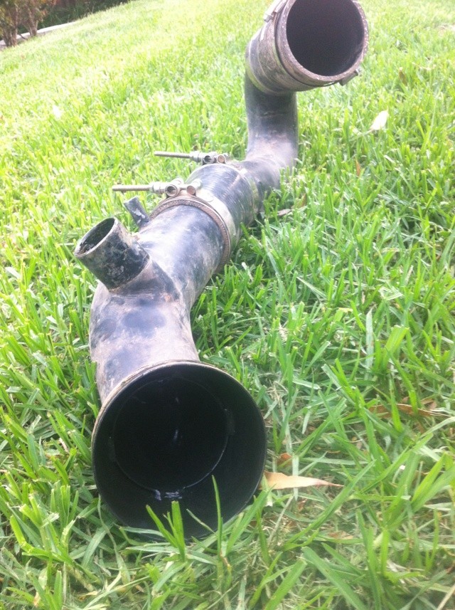
This is the existing intake pipe I made ages ago. It's made from 3in exhaust pipe with a 4in flared end (foreground) that mounts up to the turbo with a silicone hose and clamps. The far end mounts to the air box with a 3in silicone hose and clamps. It does the job but we all know airflow likes the path of least resistance and definitely not 180deg bends.
http://www.servimg.com/image_preview.php?i=735&u=14684539

I had hoped a 90deg mandrel bend would make life easy but I was kidding myself...
http://www.servimg.com/image_preview.php?i=734&u=14684539

So the next step was to grab some 100mm exhaust pipe and starting bending it 'the fun' way, or as those in trade call it, lobster backing.
http://www.servimg.com/image_preview.php?i=737&u=14684539

Lobster backing involves cutting straight tube at specific angles to achieve the required bend radius. You can use an angle grinder but it's much easier and neater with a cut off wheel as shown. I knew I needed a tight radius due to the limited space but I wasn't exactly sure what angle would be ideal. With a bit of a guesstimate, I decided to set the saw backstop at 12deg and cut several sections, keeping the short points pretty slim. I tidied the burrs up with a flap disc on the 5in grinder.
http://www.servimg.com/image_preview.php?i=736&u=14684539

This is the bend tacked together. The bottom left section is a parallel cut for the silicone hose to be clamped to and fastened to the turbo intake. I tacked the next 2 sections on before testing fitting in situ. From there, I placed and marked each section in the desired location before removing and tacking into position. It's literally like stacking blocks on top of each other forming the shape you need.
http://www.servimg.com/image_preview.php?i=738&u=14684539

The great thing about Lobster Backing is you can twist and turn the bends any which way you need.
http://www.servimg.com/image_preview.php?i=739&u=14684539

Looking inside you can see there is next to no compromise in flow. Of course, that changes if you use larger sections to shape your bends.
http://www.servimg.com/image_preview.php?i=740&u=14684539

The nest step was to weld it all together. I used the mig and stitched it together in sections, letting it cool every so often before continuing welding. This really isn't a job for a stick welder unless you're very game or skilled. It looks like crap now but I'll hit it with the flap disc tomorrow and she'll look a million bucks.
http://www.servimg.com/image_preview.php?i=741&u=14684539
 
Upon pulling the lid off the existing air filter box, this is what I was greeted with. I think I forgot to clean it after the week away at Xmas. Anyway, after removing it, the inside of the filter was spotless, as was the intake pipe so I guess those K&N filters really do work well. Haters gonna hate :flipoff2:


My choice of filter for the new air box is one from a late model Commodore. I'm using a Ryco filter to start with as it's likely to get damaged during the build. The part number is: A1358. It's the same part number for the V6 right up to the 6L V8 engines. For a $20 filter it looks well made and quite solid and a was great to have on hand for the next phase. Here's the specs on the filter from the Ryco website.


Using the Ryco filter, I could map out the preferred size and shape of the new air box. With that done it was just a case of marking it out on a sheet of steel. This was a piece of 3mm I had kicking around that had gone a bit rusty. So I hit it with the wire brush on the grinder before slapping a coat of metal primer. The metal primer also makes it easier to see your pencil marks. PS: you can easily use 1.6mm -2mm sheet for this and save a bit of weight. With 3mm, it's ahh... pretty soild :eek:


Once cut and scored, I began folding it into the required shape.


This is it folded, welded and cleaned up. In the front of the pic is the support frame for the air filter. It's in 2 pieces so it can be fitted inside. At this stage I filled it with water just to see... and was pleasantly surprised with my handiwork :steer:


This is the filter frame sitting in position. Once I finalise the securing system, I'll weld the frame in and seal it with good old Sikkaflex.


I've angled it for several reasons; 1) to reduce the final width of the box, 2) eliminate any more bends than needed getting air into or out of the air box. In this case, the snorkel feeds in from the left, and the turbo sucks it through from the other side (underside) on the right.


Next installment will be mounting it in the engine bay and making the inlet and outlets. TBC...
 
  • Like
Reactions: RFB
I had a few ideas how I was going to secure the air filter into position but space was an issue, as was the angle of the filter. In the end I went back to one of my initial plans and got on with it...

Using some 25x3 flat bar, I made a 'compression frame' to fit over the rubber edge of the filter. I then riveted on two small barrel bolt latches and welded on 2 stop beads to the bottom.


I then welded a piece of 20x3 flat bar at the bottom of the filter box. Its just a bees dick lower than the line of the rubber seal. The bottom of the compression frame slides under the retaining lip up to the stops. When the frame is folded forward against the filter it sandwiches it firmly against the steel frame the filter sits in.


I then drilled the locating holes for the barrel bolts after welding in a small section each side. I also put a slight concave in the compression frame to ensure a good seal along all edges. Here it is installed and it's quick and easy to R&R when needed.


Then it was on to making the lid using the same process as the air filter box.


Next task will be fitting it under the bonnet and completing the pipework from the box to the turbo.
 
The rain has been pissing me off to no end so decided to nut out the best way to secure the lid whilst making it easy to access and keeping it sealed...

The existing air box used a single layer of foam that the lid compressed into to form a seal with 4 screws in the top. While it worked, access was fiddly and I had a better idea for the new air box. Here, I've used a double edged foam seal. Shown is just a dummy setup, with the finished item wrapping right round the top of the box and the underside of the lid. With the lid in place, the lip of the upper and lower foam seal interlocks and the compression of the latch system seals the deal, so to speak.


One end doesn't have much room so any sort of manually operated clip system will be be too hard to get to. So I decided to use two opposing hooks to secure one end. I made these from 1.6mm SHS.


At the other end I used these adjustable compression latches. Ideally, I would have liked to use these at the other end as well but it wasn't possible. Regardless, I'm confident I'll have a water tight seal once finalised.
 
Got the mounting points welded on. There's three in total, bolting to the DS inner guard using factory mounting points with old front shock bush rubbers between the guard and underside of the mounting feet. The mounting points are made from 25x6mm flat bar with old shock bush compression plates welded to the bottom.


The third mounting point and the outlet cut for the inlet pipe to the turbo. That was fun with a 5in grinder.


4in outlet welded into place. Ended up being a 45deg cut positioned on an angle to line up with the pipework comming up from the turbo.


Then it was time to finish the lobster backed pipe from the turbo to the air box. Took a while to get the beveled sections configured to line up with the outlet on the air box, but persistence paid off. I will join it with a humpbacked coupler which will allow for movement within the join during engine operation.


Welded and ground smooth. Not the neatest but good enough considering it'll be down low and out of sight.


In position for the final check before the tidying it up and painting. I'm very happy with how direct it is, doesn't get much better than that.


The view from inside the air box looking down the ducting. Still need to smooth the insides up with the die grinder. Pretty happy with the outcome. Ended up reducing the pipe length by 2/3rds and increased the diameter from 3 to 4in.


I've decided to redo the piping from the turbo to the intercooler as well now, before getting on with the snorkel. Mainly because I now have to redo the pipework for the external waste-gate since I've changed the airbox pipework. It's currently 2.5in but I'll redo it in 3in. This will also allow me to make it a little more compact and maybe even improve flow a little as well.
 
I managed to most of the ducting from the turbo to the intercooler done today, using 76mm x 1.6mm exhaust pipe.
This was the original. It has performed well but I've wanted to make a 'better one' for a while, and having to change the location of the BOV made this the perfect opportunity to do so.


But first a little tip for those thinking of having a go. The trick to getting neat, uniform joins is to ensure the beveled cuts are parallel. To achieve this, you need to cut exactly 180deg of the opposite side you just cut. Some suggest marking a line halfway along the length of the pipe and line it up with a fixed reference mark, but there are better ways...

At one end of the pipe I tack welded on a small tab. With the pipe set up in the saw and a small level sitting on the tab, rotate the pipe until level. Clamp it off and do the cut...


Then rotate the pipe 180deg, switching the level to the other side of the tab (so you can see it), and adjust for level before clamping and cutting again. Then just clean the cut ends up with a flap disc and file for a perfect and repeatable section every time.


Here's the first section tacked together. I started from the intercooler and made the 180deg bend back down towards the turbo. The more sections, the smoother the radius. The thinner the pointy end, the tighter the radius. These are 12deg sections. It was literally built piece by piece, rotating and aligning 2-3 pieces at a time, marking then remove to tack together before adding to it.


This view shows each how section has been rotated to follow the path required and get round obstacles.


I then started from the turbo outlet and worked my way back towards the other section. It was a bit more arse than class, but I got lucky with the straight section fitting first go. I left the top section of the smaller bend loose so it could be rotated to line up for a perfect fit.


The top one is the original I made a couple of years ago. It has performed faultlessly but, as always, bigger is better. Hence the new one, below.


2.5in vs 3in. Might not seem like much but the difference in flow is significant. Will it make a difference in this application, only time will tell.


In position. Now just have to plumb the BOV back in.
 
Got the BOV plumbed in - what a mission those two little pipes were with their huge bevels, twists and turns and bugger all space :eek:


This is the finished intake pipe from the air box to the turbo.


The inside of the intake pipe was a bit scrappy as I was too lazy to turn the welder down when I first made it and so blew a few holes I had to weld up, making a mess in the process. I also wanted to smooth out the transition of the BOV pipework.
Each end before...


In typically fashion, I got carried away and went right over it, smoothing out any and all irregularities I could find. The good thing about 4in pipe is you can reach right inside with the die grinder without issue.
Each end after.


And one last trial fit before painting.


Next it's time to look at the snorkel and see what my options are depending on where the mounting holes in the guard are...
 
I pulled the Safari snorkel off and started mapping out for the custom 4in snorkel. Note, the piping and silicone bends are for planning purposes only. Should I go ahead, the pipe will be shiny new with welded mandrel bends, maybe even stainless steel :steer:

I was about to start cutting the inlet into the guard bigger but hesitated. I've never hesitated before so I did some more marking and planning before packing up and going away to think about it some more :meh:


Initial thoughts are to take advantage of the Safari mounting holes and weld tabs onto the 4in snorkel to mount it to the guard, as shown with the small penciled circles on the masking tape top and bottom.

There's also a hole at the far right underneath that's hard to see.


Thinking out loud; on the Safari, the inlet ID at the top is 76mm and the outlet ID at the guard is 70mm, but in between the dia seems close to 4in. As a compromise, I could just make the outlet 100mm on the Safari snorkel and join that straight into the airbox. That would be the easiest compromise. I can see why FatFabz recess the snorkel into the guard as it keeps it closer and neater against the A pillar as it goes up the window. The flip side is I've nudged my front guards against enough hard surfaces to know I need all the strength I can in the guards. The other option is to recess it into the guard and then weld the guard to the snorkel but that's a whole guard off and respray job - and a right bloody mission...
 
So I bit the bullet and went shopping for 4in 316 SS tube. Rang about 6 local and far away places, all of them had some part but not others or wanted a small fortune. I finally got hold of a local joint I'd never heard off before that had everything and was reasonably priced. I was also seconds away from buying a TIG welder but decided to give the MIG a go. I got the SS MIG wire but decided to try welding with the Argo-shield gas I have rather than the proper mix which was going to lighten my wallet over $200 for the privilege. The guy in the shop said it'll work fine, it just won't give you a neat weld - but perfect if you're grinding them smooth anyway.


I got 2 x 90deg bends and 2m straight tube (not all shown in pic). I needed 2 x 45deg and 1 x 90 but it was heaps cheaper to buy a 2nd 90deg bend and cut it in half. I did this by marking the centre of the inside and outside radius. I then cut a 10mm section of straight tube, cleaned the edges up and cut a slot. This allowed me to open it up a little and slide over the bend. After lining the ring up with the 2 marks, I simply marking it all the way round before cutting it. Easy as.


Next was the leg trembling experience of taking to the front guard with tin snips. I made a point of taking my time and not rushing it. In doing so I was rewarded with a neat finish I was very happy with, thankfully. Surprisingly, it hasn't weakened the guard anywhere near as much as I thought it would. In any event, I have a few tricks up my sleeve to reinforce it for good measure. I used a section of tube with a 45deg bend tacked on one end (that would be the section that goes up beside the window) as my template to where I needed to cut.


Actually cutting and fitting the tube was the easy bit. I sat the 90deg bend through the guard and marked the end once I was happy where it sat (you can see a small pencil mark at the top of the guard in line with the butt join). I then tacked a 45deg onto a section of tube and marked where it finished on the guard. I then cut a section of tube to the size between the 2 pencil marks.


I tacked the straight tube to the 90deg bend and sat it in position. I then got the window section and sat it in position and lined it up with the horizontal section of pipe. I then marked moth sides of the join in several locations before removing and tacking it together. The multiple witness marks makes realignment on the work bench more accurate and reliable.


I then trimmed the upper section before tacking on the other 45deg bend to the top. Here it is all tacked and ready for welding :bounce2:


Next, among other things, is the painstaking work of grinding the welds back to a seamless finish...

PS: If you leave that masking tape on in the sun for a day, it's going to be fun removing it. Don't ask me how I know :eek:
 
:clap:Nice work! I like the custom look of the stainless pipe.
 
Damn, great job documenting your work. That intake looks awsome.:clap:

Sent from this fast HTC thing using IH8MUD
 
You win
 
Holy Crap dude, I bet you were nervous cutting up that fender!!!

Curious, do you think a 3" snorkel pipe would fit INSIDE the fender, pretty much following your route and then pop out near the wind shield?
 
Thanks guys, I'll update a bit more tonight. Mostly done though.

alai76, I'll get back to you on the 3in pipe inside the guard.
 

Users who are viewing this thread

  • Back
    Top Bottom