1978 fj40 voltage regulator aftermarket. Wiring schematic or best guesses (1 Viewer)

This site may earn a commission from merchant affiliate
links, including eBay, Amazon, Skimlinks, and others.

Joined
May 11, 2002
Threads
126
Messages
887
Location
twin cities
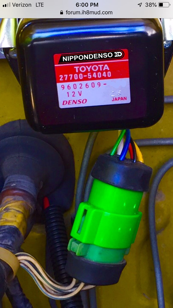
Bought this Volt Reg from one of the usual suspects dealing in these aftermarket things... 1978. 6 wire... it seems well made and the body fits nice. But...

anyone know what these colors wire may correlate to the stock harness ? Nothing on packaging or body of assembry or wires

thansk
Eaj71

F1197ED0-74F7-4F82-AA14-40269E5E7A4A.jpeg


3C13D393-CCEA-4439-A9A1-A7E2BC3A3C4A.jpeg
 
This has been addressed in this forum . LINK HTH!!
 
That's a late '78 VR. From 5/78 on. Early '78 is a three wire plug. It needs to match your wiring harness for easy install. The small clear plug is for your noise capacitor.
 
This has been addressed in this forum . LINK HTH!!
No it really doesn’t. It helps , but the question is.... what are these colors from this aftermarket VR and what’s stock colors do they fit into on the harness....cruiser corps staff doesn’t know or didn’t care to try to seriously help
 
No it really doesn’t. It helps , but the question is.... what are these colors from this aftermarket VR and what’s stock colors do they fit into on the harness....cruiser corps staff doesn’t know or didn’t care to try to seriously help
Look at the connector in upper right hand corner of the first picture of the link. Match the connector pin labels to the color of the wire coming out of the regulator. Then scroll down to the wiring diagram and match the original colors of the wire to the labels. Match up the labels and you will have the old color to new color.
 
I get that , . but that is not the issue, the problem is... is that the colors OUT of the VR are essentially random. with no backup data as o this ALPHABETICAL Coding and the COLORS do NOT match - for example - SOLID YELLOW does NOT line up with Black/yellow stripe. No real help from the VENDOR/
 
Who cares if the colors don't match? Match up N for N, E for E, F for F and so on. Then you will have the "new colors" from the regulator to the original colors from the vehicle.
 
You can buy that exact voltage regulator as a reman Denso from your Toyota dealer for less than $30. I just bought one as a spare for my late(r) '78.
 
You can buy that exact voltage regulator as a reman Denso from your Toyota dealer for less than $30. I just bought one as a spare for my late(r) '78.
Steve,
Could you share the Part Number for that please? Fellow 78 owner - I would like a spare also

Thanks
 
Who cares if the colors don't match? Match up N for N, E for E, F for F and so on. Then you will have the "new colors" from the regulator to the original colors from the vehicle.
exactly, the colors are useless - the most important thing are the CODES, which the vendor doesnt know.
 
1605285474162.png
 
$38 at Toyota in St Paul...
 
This is from the 1979 factory manual...
79FJ40VRHARNESSPLUG.JPG


This is the harness connector with the wire colors shown as if you are looking directly at the connector side of the plug. You don't say in your first post but I'm assuming you don't have the factory connector on your harness any longer. The plug on your new VR would mirror this - i.e. left = right & right = left. Note the different sizes of the connector openings. Orient them to the aftermarket VR connector housing openings and connect your wires to the corresponding pins. The 1978 manual only shows the 3 wire VR so this is the best I can find for you. I can't remember for sure but I believe the later 1978 VRs only had 5 wires despite the 6-pin connector housing.
 
Again from the 1979 manual...
79FJ40VRSCHEM.JPG


Here's the codes. The wire colors are harness colors. The connector is not shown (or you can think of it as "integral"). Again, only 5 wires to the VR.

EDIT: I just noticed that there's a typo either in the connector pin-out image or on the schematic. There is no "W" wire on the schem but there are two "WL" wires.
 
exactly, the colors are useless - the most important thing are the CODES, which the vendor doesnt know.
You don't need the vendor because the codes are provided in the link that I posted. Match the connector that you have to the picture. The terminals for each connector are labeled with the code in the picture. Then scroll down to the wiring diagram and do the rest of the mapping.
 
This all works if the aftermarket VR put the wires in the correct place. No way to check as they are not labeled and the vendor does not know
 
This is from the 1979 factory manual...
View attachment 2494513

This is the harness connector with the wire colors shown as if you are looking directly at the connector side of the plug. You don't say in your first post but I'm assuming you don't have the factory connector on your harness any longer. The plug on your new VR would mirror this - i.e. left = right & right = left. Note the different sizes of the connector openings. Orient them to the aftermarket VR connector housing openings and connect your wires to the corresponding pins. The 1978 manual only shows the 3 wire VR so this is the best I can find for you. I can't remember for sure but I believe the later 1978 VRs only had 5 wires despite the 6-pin connector housing.
Thanks
 
please see link below for further TECH :

Matt I have send 5-6 emails to your business email and have still had no response. I hope I might get a response from you here. I ordered a Voltage regulator on the 23rd of Nov for a 8/76 FJ40 I am just trying to find out the status if you could let me know I would really appreciate it thank you.
 

Users who are viewing this thread

Back
Top Bottom