Trippster
SILVER Star
Hello all,
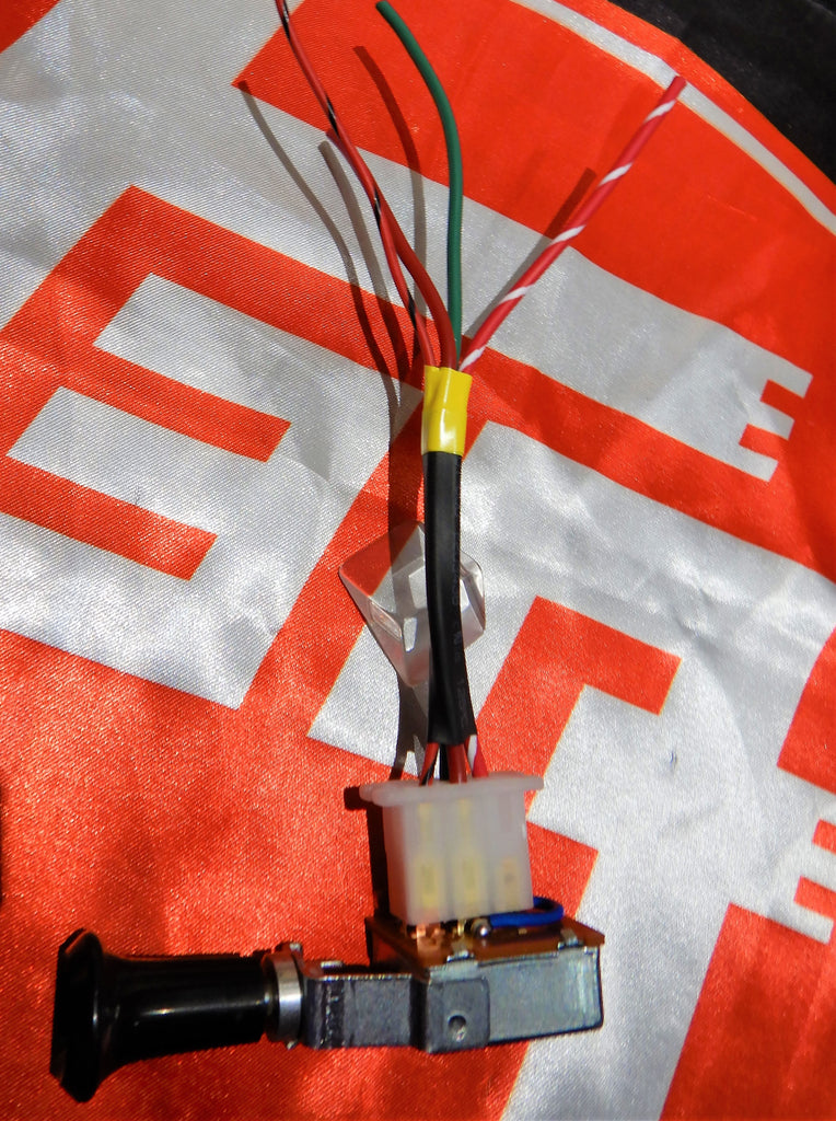
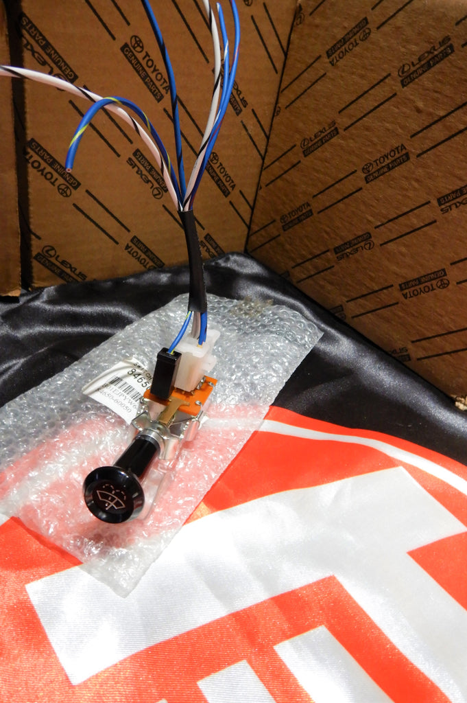
Im trying to connect Painless harness to my 68 FJ40
can anyone help me identify which pin connects to its respective system?
Thank you,
Ben


Im trying to connect Painless harness to my 68 FJ40
can anyone help me identify which pin connects to its respective system?
Thank you,
Ben