07 fj sas help (1 Viewer)

This site may earn a commission from merchant affiliate
links, including eBay, Amazon, Skimlinks, and others.

Joined
Nov 23, 2005
Threads
30
Messages
246
Just completed my 07 FJ axle conversion- InchWorm, Dana 60/70 ARBs etc; now I'm at the point that I need to tackle the electrical problems.
I've installed the new speed senser in the rear of the transfer case but there's some problem on where to tie the pulse wires in?
The other problem is how to lose all the old E-track, 4x4 lock lights on the dash that I no longer need?

Thanks for your help or direction - Tim
 
Just completed my 07 FJ axle conversion- InchWorm, Dana 60/70 ARBs etc; now I'm at the point that I need to tackle the electrical problems.
I've installed the new speed senser in the rear of the transfer case but there's some problem on where to tie the pulse wires in?

Can't help you with that, sorry.


The other problem is how to lose all the old E-track, 4x4 lock lights on the dash that I no longer need?

You pretty much don't need/can't use the entire stock 4WD ECU, without the stock transfer case, ADD on the front diff, and e-locker on the rear, so just remove or disconnect it. The A-TRAC switch can just be removed from the center switch console and the space used for something else (Contoura rocker switches will fit in the opening with a bit of filing).
 
Thanks, but turning the switch's on and off don't seem to affect the dash lights. I'm planning to mount the ARB switch's where the A-track and the others are.

As for the speed sensor, I read somewhere that the pulse wire connects to the cut out gray/white wire in the wiring harness on the master cylinder slot number 12. I think I found the wire but where the heck is slot #12?
Thanks Tim
 
Have to cut the wires to the lights. The ABS and VSC should be illuminated too (unless you've found sone way to maintain the front wheel speed sensors. If so, do tell) and will have to be extinguished.

Google "Sol's FJC FJ Cruiser Forum". Should result threads by sbetchtold that describe some of the speedometer issues and how overcame.
 
Mtbcoach said:
Sorry to read you've got yourself into this bit of trouble. There are few resources available on the planet to help you and Sol is one of them. Good luck...

As far as I know, Sol's is the only that didn't cut dash lights. I don't know how he tricked the computer, but did, plus his speedo is tapped to TC.

I tried pulling the front two wheel speed sensors on mine, to mimic a similar condition, and had no speedo, illuminated all CEL.
 
Inspection was never an issue for me, since OK doesn't seem to care about the vast amounts of unsafe, uninsured drivers on the road, but wanted maintain ABS and not cutting dash lights.
( reason I refuse part time on 80, too. ).

I spoke, in depth, with Currie about machining the wheel speed sensor ports into a built housing, using all 80 outers since a similar method of reading, and they claimed the it was cost prohibitive considering the lack of available market (keep in mind, a built front was nearing $6k from Currie, already).

For a total of $11k worth of axles alone, I didn't feel it was "worth it" (hahahahaha) if literally cutting lights, at least not for the caliber of build I had in mind.

After determining it wasn't a good investment on mine (hahahaha), started looking for 4x2s with high mileage, on the cheap, to transplant the axles out of my 04 F350 ( then with a rod through the side of the POS 6.0L block. Now running again) because the WMS-WMS is 63", DS drop, run an clocked, tucked Atlas, 3 link rear, radius arm (at the time, it seemed a good idea) front, coil overs at the corners.

I had found cheap 07 4x2 at auction and almost bought, but that's when the tides changed and bought an 80.

As I gain fab skills (hahahaha) I still may build exactly that, someday, as a trailer queen wheeler.

When I started considering the SAC, I really wanted to build the FJC how I thought it should've been built when introduced (I can recall being so friggin disappointed when they unveiled) but have to be a whole lot smarter than I am to do it right, being "if" Toyota would've done it that way.

On top of that, all have been, or are, for sale, except MissFJ, who disappeared from the forum years ago.


image-207908687.jpg

(At a loss for words.....still)

I'm almost done with the 80, and had intended on refocusing on FJC, doing bushing replacement, general PM (at 107k, now) and driving until one of my kids is old enough, leaving the 80 for wheeling duties.......but then Sol bumped his thread with updates and the SA itch has returned, NOT because I think it'd be the best wheeler ever, but more a necessary diversion to the reality that is my life.

Sorry for dissertation, OP. Follow link previously posted, or pick up on the latest updates from Sol here.
image-207908687.jpg
 
Last edited:
I did not cut any wires and the process of turning off the lights is pretty easy. I have everything in a spreadsheet that describe the pins and what to do with each one. I will try to post it up later this weekend.

If you want to get started now, I would suggest you start with getting your hands on the electrical wiring diagram. Then start familiarizing yourself with the Skid Control ECU wiring harness. There is a description of the connector and that will help you with figuring out with pin is #12, etc. In my build thread I also explain how I wired up the VSS in the tcase to a Dakota Digital box, then to the Combination Meter (i.e. Speedo).

Good luck...
 
Ok here is what you need to do in order to turn off the ABS, VSC OFF, VSC TRAC, BRAKE and A-TRAC lights in your dash after doing your solid axle swap. Also included is the pin for connecting a VSS installed in the tcase. This worked on my 07 FJC. Not sure how it will work on other model years.

Below are the instructions and result for each pin in connector A4 and A5 that are located on the side of the master cylinder.

Instructionsforpins_zps581af230.jpg


The image below is the definition for each of the pin locations.

SkidControlConnectorsA4andA5pinnumber_zps18b88310.jpg


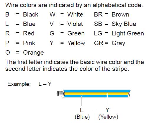
Here is the color decoder for the wire color codes in the spreadsheet above.

WireColorGuide_zpsab5e19dc.jpg


In case you are wondering where connector A4 and A5 are located. You can see them in this image. They are located on the side of the master cylinder. A5 is the small 4 pin connector and A4 is the larger 46 pin connector.

IMG_4316.jpg


When you look at the connectors, you will notice a very small square opening. I inserted a super small 1.0mm flat head screwdriver into the square opening. This releases the pin from the connector and allows you to gently pull the pin out from the backside of the connector. Pretty simple process and no cut wires.
 
Thanks, this makes things allot easier. I was trying to get by without buying the service manual for the drawings and this is what I was needing. As for the e-brake I think I can run a wire so I use the switch on the leaver.
Thanks again - Tim
 

Users who are viewing this thread

Back
Top Bottom