Caster Bushing alignment Templates (1 Viewer)

This site may earn a commission from merchant affiliate
links, including eBay, Amazon, Skimlinks, and others.

landtank

Supporting Vendor
SILVER Star
Joined
Mar 27, 2003
Threads
375
Messages
20,970
Location
Groveland MA
Website
landtankproducts.com
This started in another thread and lead to something that I've been wanting to do for some time.

The basic idea was to come up with a template that would align the bushings in such a way that the axle would rotate on it's center.

The current method tilts the axle which would exaggerate how far the pinion would move producing a greater change in the drive angles of the U-Joints.

This first set of pictures are the OME bushing in place in the template.
OME 1.JPG
OME 2.JPG
OME 3.JPG
 
The end result was that the OME yielded 3* of correction and the Slee bushings yielded 4* of correction.

At this point the templates need to be evaluated against an arm and pressed in.
 
So with this, it rotates around the axle center line, but it is not necessary the most adjustment the bushings can yield?

On my drawings I had the OME bushings as 3.4 and our bushings at 5 degree change.
 
I thought that you were making plates that would be used for drilling new holes while retain the stock bushings?
I was leaning towards not using the OME CC bushings due to the harder urethane but it looks to me like moving to Slees maybe to much.
 
Last edited:
So with this, it rotates around the axle center line, but it is not necessary the most adjustment the bushings can yield?

On my drawings I had the OME bushings as 3.4 and our bushings at 5 degree change.

Here is what I did Christo and did it again just now to verify this mornings drawing.

I used metric units on this project.

I drew a horizontal line (0*) 185mm long

I then drew another line that was 185mm long but at an angle.

I then placed that second line so the two mid points crossed, which I believe to be the results of how we have been pressing in the bushings.

The measured distance between the ends are as follows:

at 3* the distance was 4.84mm
at 4* the distance was 6.4564mm
at 5* the distance was 8.0696

These distances would equate to the needed offset of the bushing to produce that change.

I measured the OME offset to be 6mm
and the Slee offset at 7mm

I'm sure there is an equation out there that you cold use to calculate this but I don't know it.

It's basically 1.61mm/degree within that range so:

OME = 6mm/1.61 = 3.72*

Slee = 7mm/1.61 = 4.34*

As I posted in the other thread this was not about maximizing the change of the axle on the arm.

It would seem though that any benefits of using this method on OME bushings would be lost unless you didn't need that extra .72*.
 
I thought that you were making plates that would be used for drilling new holes while retain the stock bushings?
I was leaning towards not using the OME CC bushings due to the harder urethane but it looks to me like moving to Slees maybe to much.

That's been done and sitting in the garage on the truck and on the shelf. This was trying to come up with an aid for those who have or will be installing bushings. That's been a bugger for quite a few. I thought that I might be able to improve on how they have been pressed in as rotating on the axle's center has less influence on drive angles. But it would seem that with the OME bushings the cost might be too high.
 
I'm going to design up some new templates with the traditional pressing alignment that will give more caster.

I wasn't sure everyone got what I had done from those pictures so here is a side shot. The bushings are pressed into the template and held in place quite well so you can get an accurate alignment when pressing them in.

I think they will help those who need a shop to press them but the shop doesn't understand the alignment of them.
Slee bushings 001.jpg
 
Comparing what you have and the measurements that I took on my truck it would seem to me that most people would not need the extra .72*. In fact 2* was the sweet spot for UJ angles but 3* is what was needed to meet the minimum factory castor spec of +2. Now remember my 80 has heavies up front, mediums in the rear and no sliders, front bumper or winch right now. I think most people would need less caster than I do and therefore maximizing the CC at 3.72 would only put them at worse UJ anlges and +4 castor. Perhaps this explains the many of the driveshaft vibrations scenarios we have seen recently.
 
There is still the issue that we have found that the measured and drawn up angles of the caster devices does not relate to measured caster on a machine. When we do the ome bushings and do a pre and post measurement we get a 2 degree change. The pattern follows the same for plates and caster arms. I know what Rick said he did not get it, but we have done a number of trucks pre and post and always get that.

Also Rick, I assume the offsets you mention are just offset in one direction? I did basically the same as you with the lines and tilting them.
 
There is still the issue that we have found that the measured and drawn up angles of the caster devices does not relate to measured caster on a machine. When we do the ome bushings and do a pre and post measurement we get a 2 degree change. The pattern follows the same for plates and caster arms. I know what Rick said he did not get it, but we have done a number of trucks pre and post and always get that.

I still feel that this is do to the fact that the arm moves in relation to it's original position. So what you see as a degree change between the arm and the axle is not what you see on the truck. This is clear with your plates. As the axle rotates the arm drops. The amount the arm drops gets subtracted from the total angle that was generated between the axle and the arm, this gives you the change in caster. So if the axle is tilted 7* on the arm it might only influence caster by 5*

I'm confident that rotating the axle on it's center and maintaining the arm's position will give predictable results.


Also Rick, I assume the offsets you mention are just offset in one direction? I did basically the same as you with the lines and tilting them.

Not sure what you mean. At either end of the lines the distance between the two ends would be the amount of the offset in the bushing to make that angle. I reworked it again today on your blue bushings at a higher display resolution and it came up at 4.34*. That would be axle to arm and not mounted on the truck.
 
I also like a lot the idea of the soldered copper tubing to ensure the correct distance between holes. That together with your templates (yes, is redundant) seem to be a great combo.
 
Slee are you saying that once the weight of the truck is applied to the bushings the back bushing presses down and the front pushes up so that you see a -2* castor change verses what was measured with no load applied?
 
*blinks confusedly*

can you go over that in retard terms? I read it all twice and I still don't get it. Sorry, I'm kind of a moron.
 
Slee are you saying that once the weight of the truck is applied to the bushings the back bushing presses down and the front pushes up so that you see a -2* castor change verses what was measured with no load applied?

No, I am saying that if you draw it out and you measure the angle that the axle rotates it is not the same as when you measure it on a alignment rack.

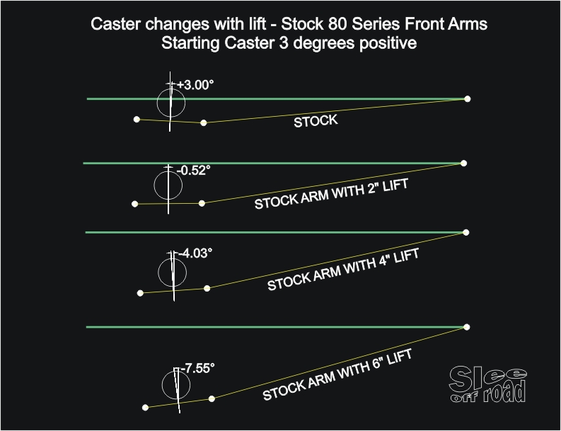
caster_with_lift.jpg


If you look at this drawing, this shows the control arm at stock caster (3 degrees) and then the effects of lifting the truck to different heights.

So with 6" of lift we would expect to see close to 11 degrees in caster changes when we measure it on a rack, however we don't.
Measured on the rack we see closer to 6 degrees change in pre and post measurements. But our arms are designed with 11 degrees of change, and when we put them on the tuck, the caster is back to stock.

I can see Rick's point on the arm moving down when you use the caster plates, but that does not happen with our arms.
 
Let me try this from another perspective.

Slee's caster plate works by lowering the front mounting point of the axle which in turn raises the front of the axle in relation to the arm.

Now if the leading arm was held in space in a fixed position then the tire would come off the ground because we just raised the front of the axle.

But that's not the case, the tire is what is fixed in place so the arm actually moves down. That downward movement has a canceling effect on how much caster is created.
 
The other thing you need to watch for is that as you rotate the axle you start to straighten out the spring. This takes some of the arch out of it and the spring will better support the weight giving more height.

I saw this with my truck. That added height will also increase the need for caster and look like you fell short if you don't plan for it ahead of time. From my experience you should add 1* to compensate for this.
 
I still feel that this is do to the fact that the arm moves in relation to it's original position. So what you see as a degree change between the arm and the axle is not what you see on the truck. This is clear with your plates. As the axle rotates the arm drops. The amount the arm drops gets subtracted from the total angle that was generated between the axle and the arm, this gives you the change in caster. So if the axle is tilted 7* on the arm it might only influence caster by 5*

I'm confident that rotating the axle on it's center and maintaining the arm's position will give predictable results.

I can see that rotating it on the back bolt is like a scissor and the front of the arm drops down a little in the front.

However with our arms that is not the case. With the arms we did not rotate the axle, we designed them to put the axle exactly in the same orientation (rotation as seen from the side) but 6" lower under the truck.


Not sure what you mean. At either end of the lines the distance between the two ends would be the amount of the offset in the bushing to make that angle. I reworked it again today on your blue bushings at a higher display resolution and it came up at 4.34*. That would be axle to arm and not mounted on the truck.

I understand what you did and measured, I just wanted it clear for people reading it.

The offset you measured is 6mm, being the measurement from the offset hole to center of bushing. Not the combined offset of using two bushings in opposite directions. The nett angle of rotation does not change.

There is also another effect on caster and that is the rake of the truck. I think this is also a source of inconsistent result from using caster correction methods.
 

Users who are viewing this thread

Back
Top Bottom