Am I overthinking my electrical? (1 Viewer)

This site may earn a commission from merchant affiliate
links, including eBay, Amazon, Skimlinks, and others.

Joined
May 12, 2021
Threads
11
Messages
92
Location
st louis
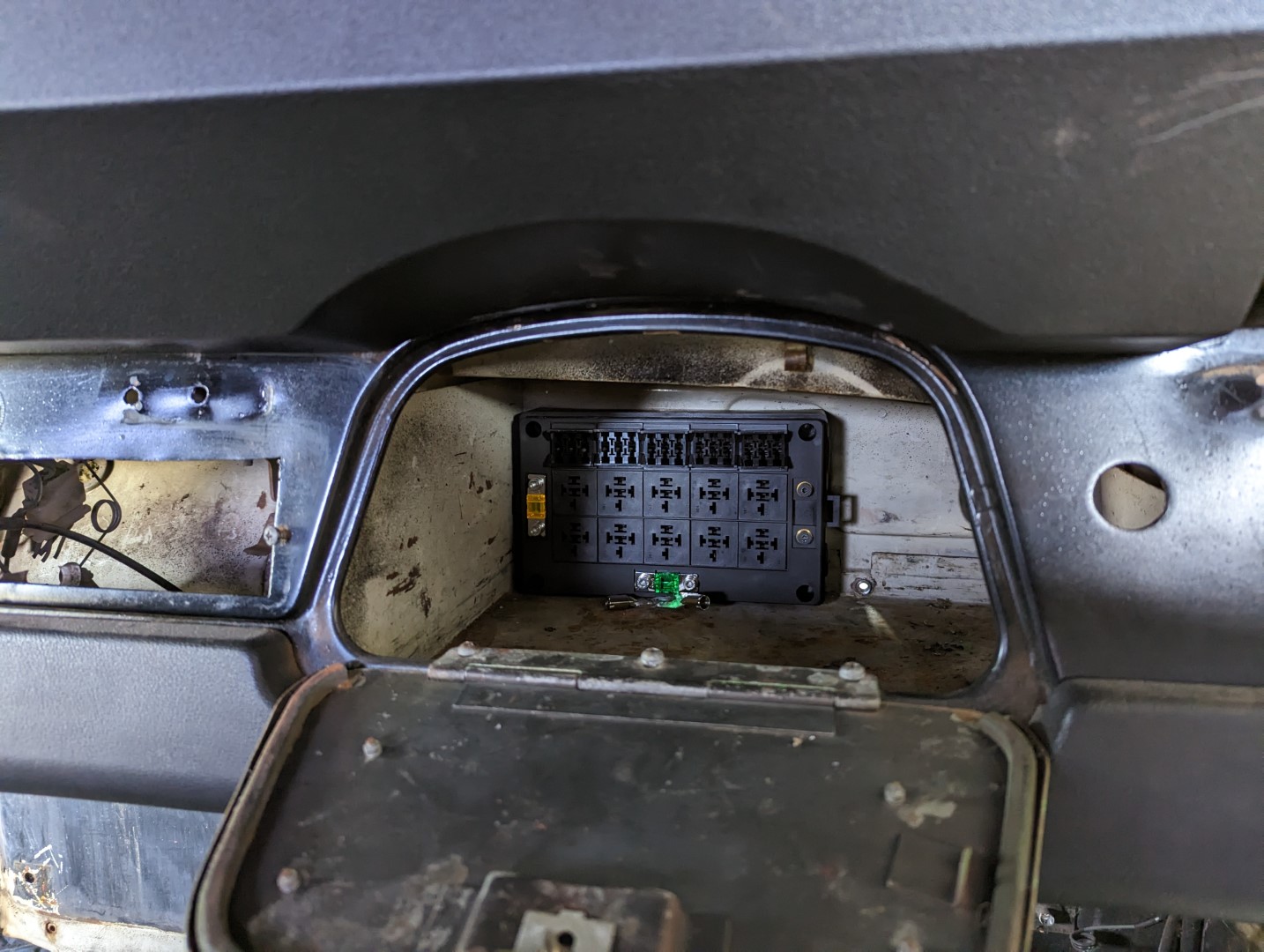
I've been chugging along on my 1970 V8 build and it's time to do the electrics. None of the existing system is salvageable (I don't know what the PO did, but whatever it was didn't involve fuses) so it's a total rebuild. I have a strong background in low voltage electric and everything going back into the system is LED or limited high current devices .
Here's the rub.
My brain tells me if it has a fuse, it has a relay, but every single harness I look it has maybe a handful of relays at best where I'm looking at somewhere around 12 after you account for the lights, blowers, horn, etc. I know that the current load should be well within range of what a dash switch can handle, but it feels wrong not to relay a load, even though it makes things more complex, costly and difficult to wire, albeit it not excessively.

If it was you, and you are starting from scratch, what would you do?

pxl_20230101_194353957.jpg
 
The 2 major issues I have are powering the headlights thru the switch and not using a relay and poweing the lights directly from the battery. Its seem most auto manufacturers wire their headlights this way too. I installed Toyota's headlight kit that uses relays with a direct connection to the battery. I highly recommend this inexpensive upgrade. The other issue is Toyota using an ammeter in the FJ4X and charging the battery thru the harness.
 
I bought a '73 with just a brake light switch, pair of rear Jeep/trailer lamps, and ignition switch.

I can't actually read the early wiring diagrams, but, I'd use the '75+ as a template for most stuff, then figure out the wipers. The only thing that got me scratching my head was the wipers, but they eventually worked, just one speed which is good enough.

Wiring Diagram.jpg


I guess that the V8 is an internally regulated alternator? Do you plan on measuring amps charging or discharging on the dash?
 
I bought a '73 with just a brake light switch, pair of rear Jeep/trailer lamps, and ignition switch.

I can't actually read the early wiring diagrams, but, I'd use the '75+ as a template for most stuff, then figure out the wipers. The only thing that got me scratching my head was the wipers, but they eventually worked, just one speed which is good enough.

View attachment 3214404

I guess that the V8 is an internally regulated alternator? Do you plan on measuring amps charging or discharging on the dash?
yeah it's just a sbc with a 1 wire alternator so no excitor needed. I'll probably monitor current but I'll use a shunt to the battery instead of an inline meter. I know the old system was basically just switches and thick wires, but every single wire in this thing was torched and clearly overheated. I know that was due to whatever the PO did, but now I'm paranoid :) I'm sure I'm overthinking this, but it can't hurt getting the group opinion.
 
The 2 issues I have are powering the headlights thru the switch and not using a relay and poweing the lights directly from the battery. Its seem most auto manufacturers wire their headlights this way too. I installed Toyota's headlight kit that uses relays with a direct connection to the battery. I highly recommend this inexpensive upgrade. The other issue is Toyota using an ammeter in the FJ4X and charging the battery thru the harness.
I did the opposite for a vehicle that the factory relayed, and run with 18g. Basically, I switched it to run just low beams and it does it with all new 16g. wire and a simple dash switch. No relay like the Cruiser, because the Cruiser actually has a quality switch and it never needed the extra relay.
 
The 2 major issues I have are powering the headlights thru the switch and not using a relay and poweing the lights directly from the battery. Its seem most auto manufacturers wire their headlights this way too. I installed Toyota's headlight kit that uses relays with a direct connection to the battery. I highly recommend this inexpensive upgrade. The other issue is Toyota using an ammeter in the FJ4X and charging the battery thru the harness.
You'll love this. The PO had 2 ammeters hooked up, so the charge circuit went from meter 1 to meter 2 and then to the battery. Why you ask? Literally no clue.
 
yeah it's just a sbc with a 1 wire alternator so no excitor needed. I'll probably monitor current but I'll use a shunt to the battery instead of an inline meter. I know the old system was basically just switches and thick wires, but every single wire in this thing was torched and clearly overheated. I know that was due to whatever the PO did, but now I'm paranoid :) I'm sure I'm overthinking this, but it can't hurt getting the group opinion.
I'd prefer to not charge thru the harness as @pb4ugo mentioned. I hate knowing that the meltdown is behind the dash and not where I can extinguish it easily. Happens frequently.

I think that much of the work here is just figuring out the length of wire to run, and where to run it. Hence a "harness layout diagram." Other FSM contain this information. Once you get that, you'll have the tools to manufacture what you need.
No worries there, I even sourced an auto rated custom harness plug. It's more trying to figure out if I should relay every fused circuit or allow the switches to push current. I suppose though if I find that a switch is not happy, I could always just relay it later. I won't be approaching the max current rating of any of the wires and the fuses are all low amp.
 
Yes I upgraded to an internally regulated alt. I installed an idiot light or you can use a voltmeter or nothing. . My alt charge wire goes to the batt. Checkout madelectric's websight on ideas for gm alt wiring.

@scratchhax, your paranoria concern is valid.
 
Relays are a way of using light gauge wire to trigger high amp draw devices that require heavier wiring. You run heavy wires from a buss bar or directly from the battery to the high amp device with a relay in the middle. That circuit is wired open. You then run light wire from a switch to the relay. When the switch is off the relay stays open as well. When the switch is turned on power goes to the relay and triggers it to close the circuit of heavier wire to the device and it runs.

This sort of setup allows for shorter runs of heavy wire between the power source and device and also allows for more compact smaller wires to run to your switches. Light draw items like interior lights, USB ports, and normal radios don't require much power and don't require relays. Things like high output headlights, heater blower motors, high output driving lights and electronic fuel pumps pull more power and need heavier wiring to run safely and should use relays.

Hope this helps adjust your thinking.
 
Headlights are like 100W a pair. That is like one amp, right? My relay switches must have taken in water, so they got deleted, more parts to go wrong. A poor headlight circuit is typically a dim problem, not an overheating one. I can afford good gauge wire, so just a switch is adequate for performance and I think it is less likely to fail.

The headlamp circuit is independent of the regular harness in my build, which keeps the length of wire to a minimum. It is the shortest possible wire run directly to both battery terminals.
 
I'd prefer to not charge thru the harness as @pb4ugo mentioned. I hate knowing that the meltdown is behind the dash and not where I can extinguish it easily. Happens frequently.

I think that much of the work here is just figuring out the length of wire to run, and where to run it. Hence a "harness layout diagram." Other FSM contain this information. Once you get that, you'll have the tools to manufacture what you need.
Agree. Keep 30A + from being under the dash

20221230_175603.jpg


20221230_175543.jpg
 
Headlights are like 100W a pair. That is like one amp, right? My relay switches must have taken in water, so they got deleted, more parts to go wrong. A poor headlight circuit is typically a dim problem, not an overheating one. I can afford good gauge wire, so just a switch is adequate for performance and I think it is less likely to fail.

The headlamp circuit is independent of the regular harness in my build, which keeps the length of wire to a minimum. It is the shortest possible wire run directly to both battery terminals.
Yeah I'm nowhere close to the current limits of the wire or even switches really. I'm over thinking this and just making it more complex than it needs to be. I'll relay the fans, headlights/brights and horn and just call it a day I think.
 
If you keep the stk wiring be sure to use a fusible link.

Turn on your headlights and see how hot the switch gets. Toyota's headlightlight kit is 81110-60p70. Use the part# and this sites search function for more info and results. Other vendor's here offer other options. I purchased this kit last spring for under $50. The harness is long so I trimmed it down. Let there be light, it's brilliant!
 
There are a million things to consider when creating a custom harness. From the alternator to the fuseblock, I'd make it as neat as possible. Nothing wrong with simple, just don't make it vulnerable.

I used to get shorts when I would accidentally ground the B+ terminal on the alternator, engine off, touched with wrench or screwdriver. Now that I have that covered, I don't load that short thru the fusible link from battery+. I consider it a weakness that could melt a blue white wire insulation.
 
My bad. 8 amps.

I'd consider using a blade-type fuse on the load side the fusible link for a while. Slot or glass fuses blow faster than a fusible link. That, and you can use a minimal rated fuse for the harness until you work things out.
 
Last edited:
I totally relate to this thread, I am finishing the wiring on my 71' 40 and I scrapped the whole harness and all the direct current wiring. I shaved the dash so there are no wires back there other than for gauges. A solid state switch panel and a GM column handle all direct current. No need for any other gauges because they are all Bluetooth from the Edelbrock Pro Flo 4 runing the ls6.0. Also so I dont get flamed, this dash was totally cut out and diamond plated when I got it so doing something like this was possible.

IMG_2164.JPG


IMG_1622.JPG
 

Users who are viewing this thread

Back
Top Bottom