This will be a little long because I have no way to shorten it and have it make sense. Basically, I am wanting to know how to correctly wire in the non-U.S. Toyota coil, which was designed to work with the non-U.S. distributor, and non-U.S. carb, as the final part of what is an otherwise successful 2F desmog. I have searched all the desmog threads and not found the answer I need to get this car to be “right”.
Here is a shortened version of what has been done as far as the carb/dizzy/coil combo is concerned.
Starting point was a stock U.S. 1983 FJ60 with a 2F, which I have had for 19 years or so.
All of the normal desmog things were done, as generally discussed t in the desmog thread, leaving aside the carb, distributor, and coil, as a separate issue; the stock ones were all left in place when the desmog was originally done.
Local mechanic who did the desmog suggested I get a better condition/better carb to replace the original U.S. carb instead of rebuilding it yet again.
I bought an aftermarket carb, one which is generally well thought of here, and the car ran worse, no matter what was attempted to fix that. Dead end there.
I then bought a Non-U.S. Toyota carb from City Racer, original Toyota part, part # 21100-61012, (I think), and installed that. All my vacuum related starting and idling smoothness problems vanished. Plus, there was a small but noticeable increase in power.
In an effort to improve things even more, it was decided to complete the desmog by getting the Toyota non-U.S. distributor which is made to go with the non-U.S. carb, to get all the vacuum line arrangements lined up as ideally as possible.
Bought the non-U.S. Toyota distributor (#19100-61180) to match the carb, along with the non-U.S. coil (#90919-02015) which was made to match this distributor.
A different local mechanic installed this distributor/coil duo to replace the stock U.S. pair. He’s a “Porsche mechanic” and was not sure how to wire the coil in and asked me if I knew. Not something I would know, so he winged it and wired it in as will be shown in the photos to follow.
The result was that the car ran like a bat out of hell, started instantly hot or cold (a first, since that had always been either/or), and idled smoothly. Had never run this well in the 20 years I had owned it. Pulled hills in gears it had never been able to pull them in before. Absolutely power was up by at least 10%. It was great, the improvement was hard to believe. It was great, that is, for 5 weeks, then the coil literally exploded while driving at a steady, relaxed 50mph on the highway.
Same mechanic then reinstalled the original coil, without the ignitor, and then a brand new Toyota U.S. spec coil, with the same result for each. Both these coils burned up the points within 20 seconds of starting.
As a stop gap measure, he wired in a resistor (as seen in the photos) to drop the coil voltage to 9V. This cured the points burning up issue, runs okay, idles okay, but harder to start again, and power is way down; car is now smooth enough, but slower than it has ever been. It's been that way ever since, because no one here knows what to do next.
I can’t read a circuit diagram to save my life, and I can get no local help from mechanics about this. Small town. Pictures will show how this is wired up now, with the stock coil and resistor still in place, but without the stock ignitor being wired into the circuit, since the mechanic took it off and said it was not necessary since the distributor we were using had points. (I also note that the information on the City Racer site pertaining to this non U.S. distributor states: "Points provide timing signal to the stock ignitor without carrying electrical load for the coil, thus will last practically forever”.) So, was the mechanic, who could not originally figure out how to wire in the non-U.S. coil (which doesn’t have an ignitor, and was made to match the non-U.S distributor and carb combo), was he wrong to wire that coil the way shown here (minus the resistor), and that is why the “correct” coil exploded when it shouldn’t have?
And, then, trying to go back to the U.S. spec coil with this setup, is the reason that, wired the way it is, it burns the points up unless you put in a power killing resistor; is it because he took the ignitor off, which City Racer seems to think is either not necessary to do or even wrong to do?
I’d like to put the correct non-U.S. coil back into this setup, because it ran like gangbusters with that coil in there; beyond my wildest dreams level. For 5 weeks anyway. That’s the goal. The fact that the “correct” coil exploded, seems to me to indicate there was something incorrect with the way it was wired in or installed, but I have no idea. Seems like if those three pieces, coil, dizzy, and carb are all used together everywhere else in the world that the coils would not be exploding if installed correctly.
Short of putting a matched non-U.S coil back in, I’d be willing to try using the stock U.S. coil with this setup, as City Racer seems to think works well, if I could wire it up in such a way that we could get rid of the resistor, and get the power back which should come with 12V being applied to the coil instead of 9V like I have now.
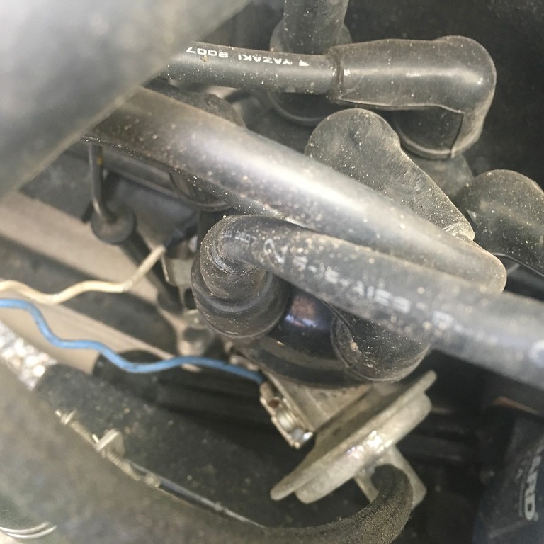
Attached are photos of the way this is wired in now, and a written description of same. Any ideas from experts here as to if this wiring is incorrect, and how to correct it, would be greatly appreciated. Any help would be greatly appreciated.
*Wire from loom (green snap connector) goes to the resistor. (Originally went to + input on coil).
*White wire from resistor goes to + pole of coil. This wire not there before resistor added.
*Other wire from loom, other green snap connector, goes to negative pole on coil.
*Third and final wire from loom passes through blue snap connector to the black cube which is attached to frame under the clamp which holds the coil in place, and passes through this cube exiting in another wire which passes through white snap connector to a wire ending in a circular electrical connector, which has been left unconnected by every mechanic who has worked on the car for the past several years, at least. (?) Where should this go?
*Second wire (is white) is attached to negative pole of coil. This goes to base of distributor, attached farthest from the vacuum line.
*Blue wire is wrapped around the white wire; is attached at one end to distributor closest to the vacuum line, and at the other end, grounded to the frame under the clamp holding the coil in place.
I feel like an idiot posting this, but have been dealing with it for over a year and a half, and the local mechanics, even the “factory trained” one, can’t figure out why the correct coil exploded, or why the U.S. spec one in there now needs a huge voltage drop to sort of work, so posting here seemed like my best bet.
Hope I can figure out how to load pictures, or this will make no sense at all. I'm new-ish here so will try using URL links to photo hosting service, since I don't yet have enough posts to allow direct posting.

Here is a shortened version of what has been done as far as the carb/dizzy/coil combo is concerned.
Starting point was a stock U.S. 1983 FJ60 with a 2F, which I have had for 19 years or so.
All of the normal desmog things were done, as generally discussed t in the desmog thread, leaving aside the carb, distributor, and coil, as a separate issue; the stock ones were all left in place when the desmog was originally done.
Local mechanic who did the desmog suggested I get a better condition/better carb to replace the original U.S. carb instead of rebuilding it yet again.
I bought an aftermarket carb, one which is generally well thought of here, and the car ran worse, no matter what was attempted to fix that. Dead end there.
I then bought a Non-U.S. Toyota carb from City Racer, original Toyota part, part # 21100-61012, (I think), and installed that. All my vacuum related starting and idling smoothness problems vanished. Plus, there was a small but noticeable increase in power.
In an effort to improve things even more, it was decided to complete the desmog by getting the Toyota non-U.S. distributor which is made to go with the non-U.S. carb, to get all the vacuum line arrangements lined up as ideally as possible.
Bought the non-U.S. Toyota distributor (#19100-61180) to match the carb, along with the non-U.S. coil (#90919-02015) which was made to match this distributor.
A different local mechanic installed this distributor/coil duo to replace the stock U.S. pair. He’s a “Porsche mechanic” and was not sure how to wire the coil in and asked me if I knew. Not something I would know, so he winged it and wired it in as will be shown in the photos to follow.
The result was that the car ran like a bat out of hell, started instantly hot or cold (a first, since that had always been either/or), and idled smoothly. Had never run this well in the 20 years I had owned it. Pulled hills in gears it had never been able to pull them in before. Absolutely power was up by at least 10%. It was great, the improvement was hard to believe. It was great, that is, for 5 weeks, then the coil literally exploded while driving at a steady, relaxed 50mph on the highway.
Same mechanic then reinstalled the original coil, without the ignitor, and then a brand new Toyota U.S. spec coil, with the same result for each. Both these coils burned up the points within 20 seconds of starting.
As a stop gap measure, he wired in a resistor (as seen in the photos) to drop the coil voltage to 9V. This cured the points burning up issue, runs okay, idles okay, but harder to start again, and power is way down; car is now smooth enough, but slower than it has ever been. It's been that way ever since, because no one here knows what to do next.
I can’t read a circuit diagram to save my life, and I can get no local help from mechanics about this. Small town. Pictures will show how this is wired up now, with the stock coil and resistor still in place, but without the stock ignitor being wired into the circuit, since the mechanic took it off and said it was not necessary since the distributor we were using had points. (I also note that the information on the City Racer site pertaining to this non U.S. distributor states: "Points provide timing signal to the stock ignitor without carrying electrical load for the coil, thus will last practically forever”.) So, was the mechanic, who could not originally figure out how to wire in the non-U.S. coil (which doesn’t have an ignitor, and was made to match the non-U.S distributor and carb combo), was he wrong to wire that coil the way shown here (minus the resistor), and that is why the “correct” coil exploded when it shouldn’t have?
And, then, trying to go back to the U.S. spec coil with this setup, is the reason that, wired the way it is, it burns the points up unless you put in a power killing resistor; is it because he took the ignitor off, which City Racer seems to think is either not necessary to do or even wrong to do?
I’d like to put the correct non-U.S. coil back into this setup, because it ran like gangbusters with that coil in there; beyond my wildest dreams level. For 5 weeks anyway. That’s the goal. The fact that the “correct” coil exploded, seems to me to indicate there was something incorrect with the way it was wired in or installed, but I have no idea. Seems like if those three pieces, coil, dizzy, and carb are all used together everywhere else in the world that the coils would not be exploding if installed correctly.
Short of putting a matched non-U.S coil back in, I’d be willing to try using the stock U.S. coil with this setup, as City Racer seems to think works well, if I could wire it up in such a way that we could get rid of the resistor, and get the power back which should come with 12V being applied to the coil instead of 9V like I have now.
Attached are photos of the way this is wired in now, and a written description of same. Any ideas from experts here as to if this wiring is incorrect, and how to correct it, would be greatly appreciated. Any help would be greatly appreciated.
*Wire from loom (green snap connector) goes to the resistor. (Originally went to + input on coil).
*White wire from resistor goes to + pole of coil. This wire not there before resistor added.
*Other wire from loom, other green snap connector, goes to negative pole on coil.
*Third and final wire from loom passes through blue snap connector to the black cube which is attached to frame under the clamp which holds the coil in place, and passes through this cube exiting in another wire which passes through white snap connector to a wire ending in a circular electrical connector, which has been left unconnected by every mechanic who has worked on the car for the past several years, at least. (?) Where should this go?
*Second wire (is white) is attached to negative pole of coil. This goes to base of distributor, attached farthest from the vacuum line.
*Blue wire is wrapped around the white wire; is attached at one end to distributor closest to the vacuum line, and at the other end, grounded to the frame under the clamp holding the coil in place.
I feel like an idiot posting this, but have been dealing with it for over a year and a half, and the local mechanics, even the “factory trained” one, can’t figure out why the correct coil exploded, or why the U.S. spec one in there now needs a huge voltage drop to sort of work, so posting here seemed like my best bet.
Hope I can figure out how to load pictures, or this will make no sense at all. I'm new-ish here so will try using URL links to photo hosting service, since I don't yet have enough posts to allow direct posting.