Builds Joel's multipurpose 40 on 41s (1 Viewer)

This site may earn a commission from merchant affiliate
links, including eBay, Amazon, Skimlinks, and others.

So while I'm working my way through fuel tank stuff, I figured I'd post a bit more on the structure progress.

It was clear that the prior owner did the cage work from the inside as none of the top side nodes were welded. That meant pulling the roof.

Yanked the hatch first. No reason to lift more than I needed to.

FJStructure37.jpg


Coerced a buddy into helping me heave ho... Not too bad!

FJStructure39.jpg


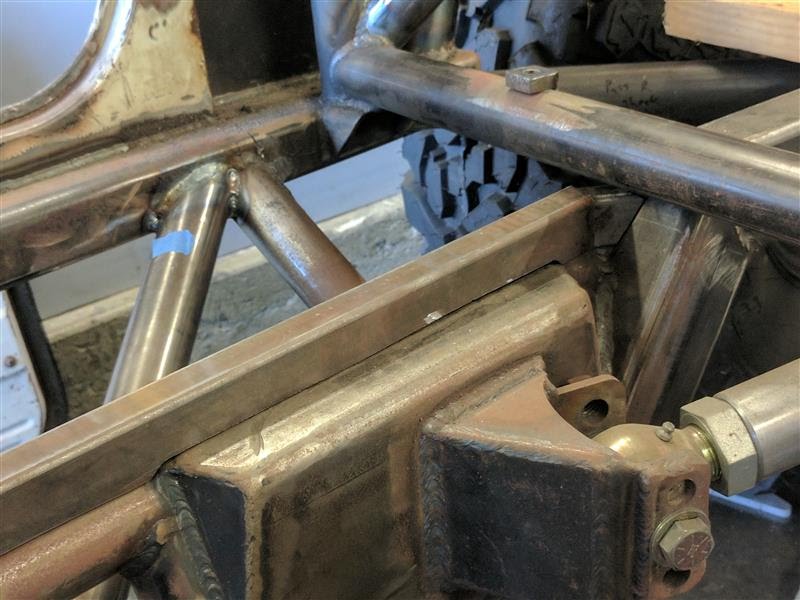
That 8 way roof node is damn cool looking. Some serious wire wheeling needed before welding.

FJStructure38.jpg


That's better. A few multi pass welds up here to avoid undercuts, but it's solid.

FJStructure40.jpg


Looks so weird with the top off. Kinda makes me wonder if I'd miss the blue if I don't go colorful in some regard.

FJStructure41.jpg


This is as good a chance as any to ask how folks are best breaking up mill scale. Wire wheels seem to work well but they're still pretty time consuming.

FJStructure42.jpg


I'm not good enough to get consistent welds with the scale still on it and I do have a great of tabs and brackets coming up in my future fairly soon.

As always comments appreciated.
-Joel
 
New job lined up (yay!) so I've been trying to knock out as much on the FJ40 as I can before time gets constrained again.

Structure is getting close but some things just take time. Case in point: my front shock towers. I was worried about cracking through the narrow cross section at the front of the mount point. It has a nasty stress riser that was just begging to break here. Check this one!

FJStructure43.jpg


So I welded on it a bit.

FJStructure44.jpg


Better but the sides being open aren't doing much for me. I can see what some folks just do hoops with tabs hanging off the bottom. That wouldn't clear my hood and this was 3/4 done so I decided to work with what was there.

Started with some random bent scrap I had leftover from something or other. Pretty much using 0.120" wall on everything here.

FJStructure45.jpg


It wasn't quite long enough so the top is made from three pieces. Side started.

FJStructure46.jpg


Liberal use of paper doll studies like usual.

FJStructure47.jpg


It's not quite perfectly symmetrical (gotta fit around the bits I have) but having one side done makes the other a heck of a lot easier.

FJStructure48.jpg


Liking the fit of that...

FJStructure49.jpg


Did some welding myself as I figured I couldn't let Steve have all the fun. Note to self. If you're welding both sides do the inside first. My pretty welds became a bit less so after I did the inside second. Live and learn ehh?

FJStructure50.jpg


Fast forward a couple weeks and I had Steve drop by to burn in the real version.

FJStructure51.jpg


Oh and I already had some gussets in the back that used pencil rod as trim. Figured it'd be nice to mimic that detail and it'll keep me from cutting open my forearms when working in the bay, so I added pencil rod down both sides. And shock towers done.

FJStructure52.jpg


Well 99% anyways. I'd still like to put in one more support aft of this assembly, but that'll depend on headers and I need to get the engine back in the bay first to check.

-Joel

Structure piece count (this round): +26 pieces
Net added to date: +57 pieces
 
Last edited:
More welding...

We burned in the motor mounts all the way. I made gussets for shear support on the top surfaces.

FJStructure53.jpg


Welded.

FJStructure54.jpg


So while Steve got into his work (bah dun dun), I played lackey and passed him stuff, including spare MIG gloves because the frame rails got mighty toasty at the mounts we just gusseted.

FJStructure55.jpg


I also whipped out a quick plate to support my winch fairlead. I was sorely tempted to make this out of carbon, but since I'd still need brackets and bolts to mount a carbon panel, simple functionality won out. I suppose I could still skin it in carbon if I want to, but it feels kinda half-assed to add pure decoration without purpose. This is only 0.060 or so it's not that heavy.

FJStructure56.jpg


We got that burned in too.

FJStructure57.jpg


That's pretty much it for the engine bay for now.

FJStructure58.jpg


I'm excited because this means I finally get to drop the motor back in so I can get moving on pedals, steering, intake and exhaust. With the new job lined up I decided it was ok to start spending money again and bought a bunch more of the little stuff I'll need going forward.

-Joel

Structure piece count (this round): +5 pieces
Net added to date: +62 pieces
 
Last edited:
More welding yet...

I had formed up some door bars a while back but wanted to check fit vs doors to be sure I wasn't blocking hardware or anything before I welded them in. Did the check. What do you know I'm blocking hardware, specifically the door latch and handle. *sigh*

FJStructure59.jpg


I can't get an exact fitment because I still need to cut down my doors. The body has been shortened by 3" which does wonders for the overall proportions of the rig, but does come with a great deal of extra work. I just mocked it in place based on the upper hinge.

FJStructure60.jpg


FJStructure61.jpg


I literally couldn't have hit this any worse. The handle pretty much lines up with the bar perfectly.

FJStructure62.jpg


After starring at it for a while. Trying to see what it would take to bias the bar up or down I just wasn't happy. I could add a bend but that's a PITA since I don't have easy access to bender anymore. Plus I like straight lines direct to nodes... Eventually I decide F--- it. I'm putting the bar where I want it (albeit biased as far to the inside as I can manage) and I'll rework the door handle as needed.

It still took some creative welding to get down around the junction at the rocker. Not perfect coverage when using stupid electrode stick-out (gas lens can only do so much) but it's not going anywhere.

FJStructure63.jpg


But this next picture makes it so worthwhile... Now that's some proper triangulation! Note the added rear shock bars down the bumper/frame junction as well.

FJStructure64.jpg


I also don't have access to the bad ass tube notcher I was using before so I got to do these with the chop saw method (well, band saw in my case). For a 1.75 to 1.75 tubing coping the base angle you need is 28 degrees. Effectively if you cut at 28 degrees off from straight on each side that's pretty close to the correct coping for a 90, then you add and subtract from each side cut for whatever angle you really need. There's more description here plus base angles for various tube sizes: Chop saw notching 101 (With pictures) - Pirate4x4.Com : 4x4 and Off-Road Forum

My favorite tip from the above thread was just to use old toilet paper rolls to figure out what you needed then trace it over your actual tube. That works like a charm, and I wish I would have figured that out sooner.

FJStructure66.jpg


Unfortunately, I did give myself one more headache to deal with. Rear seat is not so happy with the last bit of structure added. Scratch fab = making problems, then solving them.

FJStructure65.jpg


It's close so I think it's solvable, just one more thing to do.

-Joel

Structure count +4 pieces this round
Total added to date: +66 pieces
 
Last edited:
Modding by the "seat" of my pants (sorry couldn't help it).

I decided to stop being a wuss and figure out what it would take to modify my rear seat to fit. I did a great deal of looking before I picked this one (Bestop Trailmax II for a CJ) and it's about as narrow of a bench as they come. Custom = $$$, so let's see what this thing is made of.

With the back pulled off, I thought I had pretty good odds of clearing the new bars.

FJRearSeats1.jpg


So I sucked it up and started cutting out the hog's rings. Likely one more tool to pick up but I need to see if [member=83]65imp[/member] has a set I can borrow before I do. The stock CJ style rear feet are coming off too.

FJRearSeats2.jpg


Dang there's a bunch of these things. Took many more pics so I can reassemble as intended, but this gives the idea.

FJRearSeats3.jpg


For the back rest to land properly I had to get the seat further forward. This was the critical notch. I'll patch it later.

FJRearSeats4.jpg


Ended up taking a scootsch off the riser parts as well.

FJRearSeats5.jpg


But mocked in place I'm still stoked. Actually places the back seat better than it was before. I fit back there (barely) which is perfect as anyone bigger than me would be driving or in shotgun. Wife and girls are much smaller.

FJRearSeats6.jpg


And kid approved, just to be sure.

FJRearSeats7.jpg


More to come...
-Joel
 
To try to stay ahead of Steve, I've been building as much as I could just about anywhere on the vehicle that I know shouldn't be changing...

Random little one: tailgate closeout.

I built some perimeter flanges to give my panel something to bolt to and carry shear.

FJCloseOut1.jpg


I may not skin the inside so I thought the flanges looked kind boring and were heavier than needed (wanted some strength for shear but areas between bolts weren't doing much)

So I got a little creative with the plasma cutter and scalloped them all.

FJCloseOut2.jpg


Smooth it out on the belt sander (seriously, buy yourself a big combo belt/disc sander, I use this constantly). Fun fact: slag from plasma cutting throws way more sparks than the base metal does. It's kinda weird.

FJCloseOut3.jpg


Pro tip regarding stitch welding (segmented welding if you prefer the proper term): Sharpie your pattern in place. Tack whatever you're welding at the end of each stitch, then you start on the opposite end and weld until you hit the tack. Steve's either a damn clever dude or has just been doing this a while. Can't believe I never thought of that. Also FYI if you ever see a segmented weld on a drawing they should be called out as length of each weld followed by spacing of the weld centerlines. So a 1-2 weld is one on, one off (not one on, two off).

FJCloseOut4.jpg


Turned out pretty nice and saved about 1/2 a lb.

FJCloseOut5.jpg


Why is it important to take off mill scale? It melts at a much higher temperature than steel so when you weld on it, it pretty much guarantees you an undercut. Check out the one spot I missed on the perimeter flanging. Compare the vertical and horizontal welds below... Same guy same machine setup.

FJCloseOut6.jpg


While I was busy scalloping flanges, I also carved up my motor mounts. Before:

FJEngine7.jpg


After:

FJEngine8.jpg


I already pulled about a lb a piece out of these guys. I'm still debating cutting these down to only 4 bolts, but since it's offroad and loads can be violent a little extra load sharing won't hurt me, hence the finger I left on each.

-Joel

Structure part count +6 pieces this round
Net added to date +72 pieces
 
Seat mounting is making progress but I'm not 100% happy with it.

Fronts first...

I'm still trying to package the biggest 3" mufflers I can manage in the boat sides. That worked out to be a magnaflow 18x6" can. It's tight but it almost worked as is.

FJFrontSeats1.jpg


It's getting mighty close toward the back edge though, I only have the muffler shimmed up with a heavy larger of cardboard on each side as shown. I wanted more space so I segmented the mount on each fore/aft leg and suddenly it was a great deal happier. I still need to package some serious heat shield under here and I'm only going to have about 3/8" to do so. I'm also either going to have to clearance that main cross bar or shove a fast turndown in there to clear it.

FJFrontSeats2.jpg


Figuring out I could make the above cuts was all based upon a pretty nice find. The aft mount point for the front seats to the frame were only welded on the rear edge. That made it pretty simple to chisel them up into a slight angle and it left a heck of a lot less to redo.

FJFrontSeats3.jpg


Happened to notice that front cross bar of this seat structure had some healthy weld deformation in it. More than I could take out by hand so I rigged up some support and cold formed it with my jeep.

FJFrontSeats4.jpg


Much better.

FJFrontSeats5.jpg


And burned in.

FJFrontSeats6.jpg


So the fronts are in good shape. If anyone knows of a really bad ass heat insulation product I'm all ears.

The rears are giving me a debate though...

Front mounts for rear seats will be fine. Have a strategy there. The aft mount needs to serve as both a riser and let me bolt in a lap belt interface point, likely from the side. Issue is that I also have a big ass notch in my frame for shock clearance.

FJStructure67.jpg


I was thinking I'd kill two birds with one stone and make a big doubler to go on top. This is 1x3 0.120 wall.

FJStructure68.jpg


Good news is that it's the right height, should be plenty for both mounting seat to and a lap belt interface. Downside, it's heavy about 4 lbs per side, which for whatever reason gives me heartburn here since it's seems like a really inefficient support. I also can't guarantee it'll clear the shock at full flex. However if I bias it toward the inside I'm giving up room for my fuel cell and I'm not even really sure it's needed. Now that I have the rear angle tubes in, I'm struggling to picture a load path where this fails. Maybe it'd buckle in a bad rear end collision... Not sure.

I think I just need to suck it up, do the flex check, and fight for full height (not trivial). Then suck it up again and say I'd feel incredibly dumb if someday somehow I managed to have an issue at an intentional weak spot in my frame. Suck it up enough to run about 6 lbs of insurance vs. a lighter mount.

Thoughts?
-Joel
 
Floorboard risers/support structure...

Finished a big piece of what I needed to run the exhaust in the boat sides plus give my floorboards something to bolt to.

This was a piece of 1x3 I ripped in half. Bit of trimming and welding at the ends.

FJStructure69.jpg


FJStructure70.jpg


Developed a bit of an arc after it's trip down the bandsaw but nothing a clamp couldn't solve.

FJStructure71.jpg


Burned in a bunch of weld nuts prior to welding to the rig. Weird watching them smoke when welding adjacently.

FJStructure72.jpg


Need some side supports at the rockers but it's a great deal closer. Side weld nuts will be used for fuel, brakes, and/or wiring harness runs depending what I end up packaging where.

FJStructure73.jpg


Structure count +4 pieces this round (not counting inserts since I just welded them w/ mods)
Total structure +76 pieces
 
Last edited:
Getting close to the end of the structural tube work, just a few more things to do.

I was kind of proud of this round though... In the MillenWorks shutdown I brought home a couple weird looking multi bend pieces that I figured I could find some sort of use for.

FJStructure74.jpg


Figured out ways to get 6 pieces (thus far) out of these two bits. I'm also getting better at tube notching via hole saw. I found it's easiest for me to eyeball tangency and go back to mark the deepest point of the cut.

FJStructure75.jpg


Then I ADD two cut marks to make the side of the fish mount at relative angles to my first line. This way my base angle is always whatever it was I needed and I don't have to do relative math. For two tubes of the same size, it's just 28 degrees each way of added material on each side of my cut. Case in point:

FJStructure76.jpg


The above fit was done with no trimming.

FJStructure77.jpg


And now I have a solid grab point on either side of my dash structure kinda like a curved pistol grip on both sides. I got the idea from the Can Am side-by-sides, which use vertical handles as their grab points.

FJStructure78.jpg


Added oh crap handles on the A-pillar the same way. These flair inward to avoid the doors. In both cases I did some test fitting (not shown), so I think they'll be good.

FJStructure79.jpg


Next up, I've been working on harness mounting. I'm basing much of the design on Billavista's excellent off road tech series. In this case, these articles:
- BillaVista.com-Driver Restraint Systems Tech Article by BillaVista
- BillaVista.com-Driver Restraint System Installation Tech Article by BillaVista

I actually really like the sewn on style harnesses Bill reviewed as well.
- Pro Armor Harnesses Tech Article by BillaVista

Anyways, I added a bit of hardware, specific to harnesses. Both front and rear are a challenge to position perfectly so I'll be using double sheer brackets for the attachments and to get things perfect. Rear should harnesses use a cross bar in between the C-pillar nodes. I should be just below the rear wind hatch if I measured correctly.

FJStructure80.jpg


Front shoulder harnesses use this protrusion from the shock node.

FJStructure81.jpg


Barring rear seat mounting stuff, I think the rear is ready for a fuel tank, floorboards, and body close outs.

FJStructure82.jpg


Progress!
-Joel

+7 pieces this round
+83 pieces total
 
Last edited:
Kind of a random post... One of the things I inherited from the MillenWorks closure is this bitching wood plaque commemorating Rod Millen's custom Land Cruiser creation as documented in Four Wheeler magazine.

I know there have been various pictures of this rig floating around the internet for a while.

If anyone knows the present owner, I'd love to offer this to them. If I'm not successful in finding that, let me know if you're interested and make me an offer. It's way cool but I don't have a good place to put it.

FJMillenPlaque1.JPG


FJMillenPlaque2.JPG


FJMillenPlaque3.JPG


FJMillenPlaque4.JPG


FJMillenPlaque5.JPG
 
Here's the first of several updates that have been done for a while but not documented... I finally even got to start screwing with carbon fiber. More on that in a second.

Rear seat is getting close. Remember that odd ball bend I reference a while back?

FJStructure74.jpg


Got a couple more pieces out of it. Turned out the bit I had left was about right for the forward shift I needed for the rear seat.

FJRearSeats8.jpg


Burned in a couple patch panels on the side where I clearanced it prior.

Once I'd added a couple kickers to the frame and shaved down flange nuts welded into the ends, this was pretty damn stout.

FJRearSeats9.jpg


The seat frame had some side plugs welded in where I'd cut it . Added couple more at the rear seat uprights just to tidy things up a bit.

FJRearSeats10.jpg


Part of the trick in getting the rear seat to land right was planning the rear footwell. I ended up having it slope upward slightly which seemed the most comfortable against my toes and I'm kind figuring I'm a decent size model for the back seat. If you're bigger than me, you're calling shotgun.

I've been working on a shed I've been cutting up from a giant metal tradeshow backdrop (inherited from my former company now defunct). One bonus is that I ended up cutting off maybe 30 or so premade metal tabs. I have a feeling these suckers are going to be useful all over the place.

FJRearSeats12.jpg


I debated tabs vs. strips like I did on the rear tailgate ares (however that one will show and it's intended as a shear panel), this isn't so I stuck with tabs for simplicity. They are a touch harder to line up this way but I got to play with a cool tool I picked up a while back that helped with that. "Stronghand MagTab:. It's cheap at only $15 or something and works really well.

FJRearSeats11.jpg


So the carbon fiber. Why carbon fiber? Well why not? It's light, stiff, looks bitching and contrary to the big downside for most folks, mine was free. This panel is a 5 mm thick with a 2 mm core (sandwhich construction).

FJRearSeats13.jpg


Other dowsides? Well I probably won't use it directly over the fuel tank (the resin can burn making for a lousy firewall). Hit it hard enough and you can fragment the stuff. I do have a ways to go before I'm thinking bout driveshaft loops, assuming that's even possible with higher travel. Funny one, with carbon you have to be careful with your choices on nuts and bolts. You can run into galvanic corrosion using it, because of the high... wait for it... carbon content. I'm not planning on going mudding with this.

Anyways. I have a floorboard.

FJRearSeats14.jpg


Almost (needs bolts) and a rear seat (almost, needs rear mounts). Whatever, it's progress and progress is good.

Structure count +17 pieces this round (tabs count since I had to modify them)
Net parts added to date +100 pieces
 
Last edited:
WAAAAAAAAAAAAAAAAAAAAAAAAAAAAAA!!!!!!!!!!!!!!!!!!!!!!! aksejnfoaeih [-9wef 8742 fyisuhekjaheoJHOAWIDJ 892
 
Got a lil too excited there for a second. Dang that was a lot of free steel.
 
Sweet truck!
 
Took the XJ out last week and had a blast... Random pic from the adventure hoping to light a fire under my ass to keep moving on the 40 too.

DisneyDesertDays4_11.jpg
 
Last edited:
Time to get the FJ's engine ready to go in.

Reminder: base specs:

LS3 Block stroked to 416
10:1 Compression
Callie's Compstar 4" Crank
Callie's Compstar H-Beam Rods
Wiseco Pistons
ARP Main Studs
CCP Stage 4 Blower Cam (240/254 .613/.596 115)
Roll master double timing set
Melling 10296 Oil Pump
L92 Rockers with BTR Trunion Kit
LS7 Lifters
Ported L92 Heads
Manley Stainless Valves
Manly Pushrods
PAC Springs with Titanium Retainers
ARP Head Studs
LS9 Head Gaskets
24x Reluctor 1x Cam Gear

Biggest change needed was swapping out the cam. What the engine came with was too big for off road use (at least assuming I wanted to crawl as well as throw sand). I also wanted to inspect what I could and make sure things were healthy inside.

Started by pulling valley covers. No surprised here. The valve train install appears to be fresh (note the grease on the tips).

FJEngine9.jpg


FJEngine10.jpg


ARP head studs peaking out. Thus far the engine has had everything it was supposed to.

FJEngine11.jpg


Cam it came with looks nice perfect peaking through windows.

FJEngine12.jpg


LS6 style PCV system confirmed.

FJEngine13.jpg


I did check what would be involved in making hooking up all 4 steam ports. On the LS3 intake it looked like more shaving than I wanted to do. It was no where close to landing.

FJEngine19.jpg


FJEngine20.jpg


I’m also not a fan of running little AN hoses on top of the intake since it always seemed like that would be a high spot to trap air anyways (maybe we don’t care if trapped air is up out of the way). At the end of the day I decided to keep it simple and run the 2 port steam tubes. I needed block off bits for the others and found that the aftermarket pieces are cheaper than OEM. This also probably saved me a few grams on my rock crawler build.

FJEngine17.jpg


FJEngine18.jpg


Still going to have to pull it apart for the cam, but no issues thus far.
 
So the cam that that this came with is too damn big and I need torque down low. I spent a great deal of time researching cams (dedicated chatter on that subject is over here: LS2 stroker cam selection)


As part of that I decided to check the port volumes. If you have a nicely graduated cylinder that would work well. I didn’t so I did all my checks with 91% isopropyl alcohol and measured by weight.


FJEngine21.jpg


Thanks to Daniel (Mpbdy) for the recommendation. Since it was alcohol it made for easy evaporation and avoids rust. I’ve also heard of some folks using oil to be sure it can’t weep past the valves but that sounded like a mess.


Checked three ports for inlet and three for exhaust.


FJEngine22.jpg


FJEngine23.jpg


No real magic to this other than making sure you’ve turned over the crank enough that you’re 100% sure the valve is closed. Take weights before and after.


Stole a nose snarffler from my daughters to help pull the liquid when complete.


FJEngine24.jpg


Results indicate a pretty big port.


FJEngine25.jpg


Note the math above is wrong. Turns out the 0.786 g/cm^3 density I found is already for 91% isopropal. That makes my final ports sizes 282 cc for intake and 96 cc exhaust (not 257 cc and 87 cc as shown on my sheet above)


One oddity I ran across. I had a moment of panic cleaning out the intake ports and I found that the port had broken through the casting wall. WTF? You can just see it peaking out around the corner.


FJEngine14.jpg


FJEngine15.jpg


Pulled the valve covers back off to try to figure out where and figured out it’s the void beyond the tip of the rocker bolt.


FJEngine16.jpg


I debated trying to smooth or plug this somehow (JB weld maybe?), but I didn’t want to run the risk of it coming loose and getting a slug of hard epoxy down the intake.


After a bit of looking online, I finally figured out that almost all LS3 head ports do this. There’s apparently a bump intended to keep the hole blind that protrudes into the intake port. If you want to smooth out the passage this bump gets carved off. More details in this thread…


Heads ported, is it ok that they went into the rocker arm bolt area??? - LS1TECH - Camaro and Firebird Forum Discussion


So what folks really do it put some thread sealer on the rocker bolt to be sure it can’t be a leak path or a means of oil consumption. Given there’s not much discussion on what type of thread sealer I ended up using Teflon paste (aka plumber’s pipe dope).


Last test before ordering a cam… I tried to borrow a spring force gauge, but it wasn’t compatible with LS style heads.


FJEngine26.jpg


FJEngine27.jpg


I figure there’s been enough attention to detail in this engine assembly thus far that so long as I go milder than the cam the engine came with (both lift and duration), I should be fine. That’s not a tough hurdle to clear.

-Joel
 

Users who are viewing this thread

Back
Top Bottom