Builds Blender, My LX450/FZJ80 + FJ45esk + GM + Land Rover crazy concoction (1 Viewer)

This site may earn a commission from merchant affiliate
links, including eBay, Amazon, Skimlinks, and others.

I'm also on the hunt for another used LX450 or FZJ80 front passenger side coil ( the shorter one in the set ). With the way the weight in the chassis is distributed so far there is about a 1/2" difference side to side which seems a bit annoying....
 
Gotta keep doing something.....


I got all the ribs for the upper rear window panel(s) bulb seals welded in place into the cage structure.

Now I need to make the corner gussets that will locate the panels along with some extra support for the cage junctions.

I have also been thinking more about if I should try to make some rear corner windows similar to some of the fj4x stuff to improve visibility when the panels are in place. Maybe heat forming some Lexan into a curve? Then hold it in place with some lock-channel gaskets?

There are a few other small projects with the tub to wrap up, but the other big one on my mind is the top panel. I think I am going to abandon my plan to try and make a complex curve factory type shape. I think I am going to end up doing something with some more simple curves, maybe even geometric in some ways, then weld a few of the panels together to form a decent top? I just don't want it to look terrible. It will be a bolt on panel so I can replace it later if I don't love it....

Other things on the list.....

-Extend the lower door post to the extended belt line. This also needs to have a new strike plate mount for the door latch. This can be welded in, but needs to match the top of the existing body....which is a pretty complex little shape.

-Make the upper door surrounds. I think the top of the door area will be welded into the cage structure. I have thought about trying to extend a heavier piece of material beyond the top edge to act like a rub rail. I am not sure if that would look ok.....but it would be nice if you leaned the top over into a rock or tree. The rear vertical surround might be a unit that bolts to the B-pillar upright so it can be removed. Kinda like a metal version of a jeep TJ door surround? That would allow a bit more visibility past the B-pillar....and elbow room when the upper part of the door is removed?

-Brake booster/master/pedal mount
-Steering column mount
-DBW gas pedal mount

Plenty to do.....
 
Just a bite....


I welded in the rear window panel mounting plate/gussets. These are what the panels will attach to in the 4 corners. These are offset about 1/4" from the rib to allow space for the bulb seal to go all the way around the opening.

The compression of the bulb seal (panel location ) will be set but a threaded aluminum spacer that will be attached to the window panel carriage bolt. Then on the inside there will be a wing nut, thumb screw, or threaded knob.

Just one of the those details I am trying to plan ahead for....
 
Something new to work on....


I need to extend the door post up about 3" to match the new rear body line. This is a pain in the butt shape for sure. There is a little reverse bend I need to match. I also want to make a removable door surround for the upper half of the door so I figured it was worth investing a little time in making something to help me.....


Started by making a little chipboard template for the top cap. I'll need to make a few of these eventually in some 1/8" steel, but I was more concerned about having a way to transfer the shape for now....


A couple hours later I had this! I decided to make some 'pullmax' style tooling to form this shape in straps of sheetmetal. Basically, you form the metal a bit at a time using a die with limited length. I plan on using this in my little HF press in stages.


I made the dies with pretty simple tools. I basically drilled all the inside corners with a 1/4" bit to match the radius I needed. Then connected the dots with the bandsaw in the vertical position. After some file work to clean up the shape I cut off the section in the bandsaw the other direction. The same was done for the female portion of the tie after scribing the make shape in transfer. The female side required a little more work with the files, but came together pretty nice.

Tomorrow I will get everything welded into a little assembly along with round up a few springs to use on the guide rods. Then I should be ready to make one of the test panels.

The other part of this construct will just be a simple 90 part and it will overlap the formed part in the striker plate area. I am going to give myself an extra fastener for that in case I want to raise the door latch a bit too.

Once I am more comfortable with how the die works I will form the 21" tall sections for the upper door surround. I think I am going to make that a bolt in part to allow a little more elbow room when the upper part of the door is removed.....similar to how the door surround works on like a jeep TJ.
 
I love it when a plan comes together....


This is what the 'Pullmax' style die looked like mounted in a simple spring return holder. The guide rods are 0.120" wall x 0.750" pins inside some 1" OD sleeves. The springs are a #51 from the local ACE hardware store.

The entire contraption is installed in my HF 20 ton press....

I had someone ask me to make a video about how it works.


Sorry it is long and pretty boring. Overall the concept worked really well for the time invested. It makes me want to get a real pullmax machine! This is a good tool option to have in your back pocket in a home shop. I think it could be improved upon by making a universal holder for the dies. Basically something that could clamp the die. The dies could also be made of something like derlin or HDPE for sheetmetal work. That probably wouldn't ding up the material.


This was the 1st section of bend that I made...

So why all the fuss....


Since I raised the rear belt line of the chassis about 3" from stock, the door post didn't line up any longer. The little tool made the outside section of the door seal area. I bent up a small 90 section that overlapped in the door latch area and tied back into the cage B-pillar post. The top cap is 1/8" material and I kept a hole in the top to allow me to pin in the future upper door surround. I also added another 8mm mounting bolt in case I want to raise the door latch/striker up a bit.


I decided to try and push my skills a little bit by TIG welding the entire assembly into place. While I may be getting half way decent at welding on the bench, welding out of position on thin metal is still a challenge for sure. I am having pretty good luck with .045 filler for thin sheetmetal. That seems to really make a difference.


I think the TIG makes for a little easier clean up since you have more control of the heat input vs filler material height. The new air compressor is SOOO nice for cleaning up stuff like this. I was able to use a die grinder with a 3" cut off wheel to remove the proud part of the weld really quick. Then used a 2" roll-lock pad on the angle grinder with a 36gr-80gr-Scothbrite series to make things look pretty dang decent. It isn't perfect, but a little high build primer or a skim of filler....way good enough for me.

Onto the other side....
 
that's really cool! looks like it opens up all sorts of possibilities

cheers for the video ;) you have more patience than me :hillbilly: I skipped through the video in chunks

do you think it would work if you did the major bends in your bending press, then use the pullmax to finish the minor bends?
 
Just blown away. I would never have thought you could put a sheetmetal die in a manual press like that. ~15 minutes to form a panel like that is lightning fast compared to other manual forming methods!!

I'm learning a ton. Thank you @Mieser for posting your knowledge up here for others to learn from!!
 
Onto pedals and steering after I finished the 2nd door post.


Door post P. This one turned out pretty nice. It's always amazing to see the difference in quality vs time input on consecutive parts.

Then this happened....


I needed to remove the clutch pedal pivot. I found out that the pivot bolt was seized to the bushing sleeve right after it popped the weld nut off. I tried using a punch to break it loose....then an air hammer on the punch....nothing worked. My last resort was to cut out the bracket and lop the head off the pin bolt. This let me remove the entire thing as a unit....


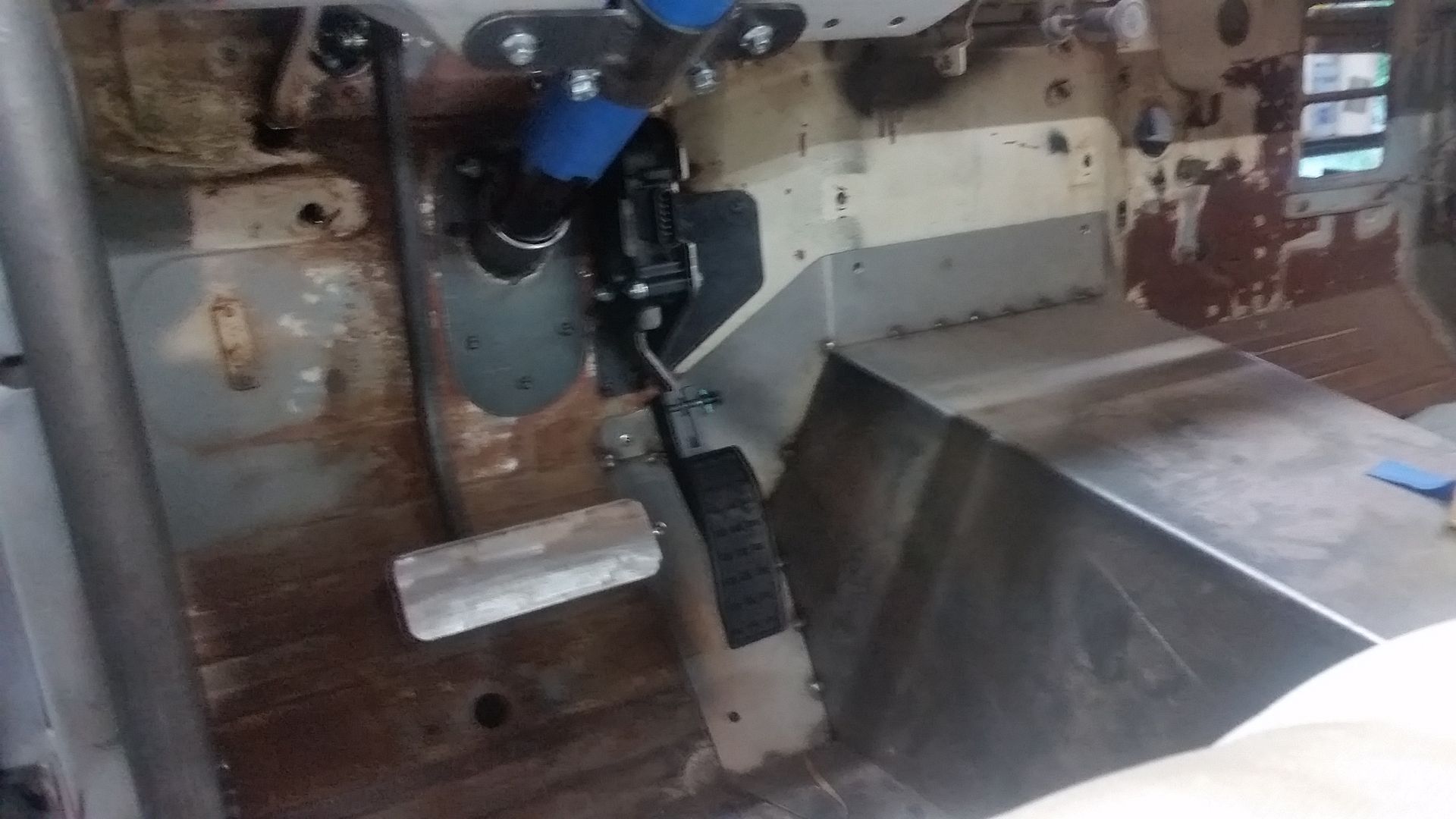
This is where I ended up this evening. The general plan. I straightened out the brake pedal in the press and chopped off the small factory pad. I then made a new pedal out of some flat bar that I crowned in the press. Then tack welded that in place on the old pedal arm after measuring a few difference vehicles to try and figure out the pedal offset. I think its close. I might cut 1/2" off the outside to give a bit better foot rest area and access to a floor dimmer switch?


I am going to use the booster and master from the 80-series chassis. It shouldn't be too hard to make an adapter, they seem to be pretty common. Mine is going to have to be a little different since I am moving things to the clutch side. The hardest part is probably going to be making an extension for the pushrod/clevis thing.
 
that's really cool! looks like it opens up all sorts of possibilities

cheers for the video ;) you have more patience than me :hillbilly: I skipped through the video in chunks

do you think it would work if you did the major bends in your bending press, then use the pullmax to finish the minor bends?

Just blown away. I would never have thought you could put a sheetmetal die in a manual press like that. ~15 minutes to form a panel like that is lightning fast compared to other manual forming methods!!

I'm learning a ton. Thank you @Mieser for posting your knowledge up here for others to learn from!!

Thanks guys. I like trying new things and figuring out ways to dumb down some industrial tooling processes. This style of die could be make in aluminum or plastic also. I am going to try and make a universal holder for dies like this. That would be a neat tool to have around. I wouldn't mind having something like a bead roller or pullmax some day though!

Doing the bend at the low point in a press before the final stroke might be a good way to go. It would help keep things inline I think. I could also add a fence to the jig to set the offset also.

The one thing to remember. I'm just a guy in his garage. I try to encourage everyone to try and build stuff. I swear this isn't that hard.
 
Another piece of the puzzle....


I was able to get the mockup done on the bracket that mounts the J80 booster and master to the FJ40 firewall....on the clutch side. With the engine mounted so high in the chassis the space on the original brake side was pretty tight. Moving it over the clutch side also moved the master away from the passenger side exhaust manifold.

The clevis push rod needs to be extended a few inches. I also want to add a few fasteners to tie my new bracket into the factory firewall brace rib.

A few more misc pictures....


Need to fix that little spot so I don't have to trim the inside studs on the booster. I really like being able to use intact unmodified OEM parts when I can ( I don't care if they come from 100 different vehices! ).

Shop tip.


If you need to mark the bottom of a long hole, take the pen apart and use just the ink tube thingy.

Next...

 
I finished off the details on the brake booster/master adapter bracket.


Final position on the booster and master. Overall pretty happy with how things turned out. I still need to make an extension for the clevis, but need to track down a fine thread metric nut for that.


I added a few other fasteners to spread out of the load a little more. There is another 8mm bolt on the large vertical wall on the rib. Also another little tab on the front flange section that uses two 6mm bolts.


It was tight to get the pushrod centered with the factory rib. I ended up having to dent the rib in two places in order to clear the long studs on the 80 series booster.

Fun stuff.

Now onto the column mount and then the DBW pedal mount. I should probably throw the seat back in soon. Anyone have any good ideas for a steering wheel. I kinda want to get the column in before I decide on a diameter. Most of the aftermarket wheels with adapters just seem kinda meh these days....
 
One more small project done....


Steering column mounts are done. I ran into a few little hick-ups. The output for the column wiring is right in the middle of the upper mount. I ended up having to trim the mount a bit when I converted it into a 2pc clamping unit. I think I am going to try and extend the dash gauge panel a bit to cover any gap on the top of the column where you might be able to see the wiring exiting the column.


Upper clamp on the back of the saddle mount. I need to pick up some more 8mm bolts for this. I will add some locking nuts for final assembly.


Where the wiring ended up exiting. A pain in the rear for location.


Scrap clamps for on my welding table the hold things down for tack welding.


A 2" wood dowel works very well for mockup. It saves a little bit of wear and tear on the column finish and is a lot lighter to work with....
 
More pedal....


I was able to get the mount mocked up for the DBW pedal done. I still need to pull it for a gusset and final welding. Overall I am pretty happy with is. I ended up using this pedal instead of the stock truck pedal. This is the GM Performance parts ( or Caddy ) version. I can use it unmodified which is nice for future replacement.

The mount ended up using 3 of the factory 6mm fasteners in the firewall with nice captured nuts. The 3rd fastener is up on the firewall 'hump' which puts all the pedal loads against that surface with the leg on the bracket.

Overall, just another time killer detail project.
 
Just finishing up the DBW pedal stuff....


The bracket is all done except paint. I even TIG welded it for extra practice. I was able to add in a gusset and a little bit of lightness with some big holes.

Now onto the next thing....
 
My weekend chore...


I TIG welded all the holes shut on the dash so I could have a clean starting point for future layout.

Here is the general technique I used....


Make a small patch panel for the hole. Making these little tiny ones for the dash pad rectangle holes was kinda fun. For these I cut out the rough size with the body saw, that seemed to give me the best edge in a part that small. These there only about .330 x .220. When filing them for final shape I held them in some small vise grips. Getting a good fit is nice when using a TIG welder. I used a magnet on the back to hold them in place for a few tack welds. I also filed the inside edges to get rid of as much of the old primer/paint as I could.


I used my tig machine to weld them in place. I have the best luck using about 1amp per .001 thickness in material for a base setting. I can back off the pedal if needed towards the end, but having enough amps to get going quickly is nice. For filler I am using .045 which seems to feed in really nice on lower amperage thin stuff.


To knock down of the proud part of the weld, I have found that using the edge of a 3" cut off disk spun by a 1/4" air grinder to work the best. You just have to be careful to stop at the right time. A little less is a lot better than too much.


Next I hit things with 36 grit on a 2" roll-lock pad driven by a 1/4" right angle grinder. These are quick and easy to change which saves times. The small discs last longer than I thought they would, but you do go through them pretty quick.


A quick hit with 80 grit to make the scratches a bit less noticeable.


Lastly I dress things out with a brown Scotchbrite disc.
 

Users who are viewing this thread

Back
Top Bottom