How NOT to restore the FJ40 (3 Viewers)

This site may earn a commission from merchant affiliate
links, including eBay, Amazon, Skimlinks, and others.

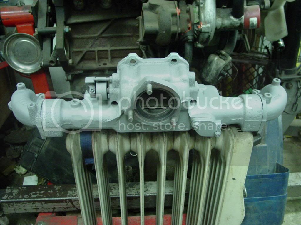
The cleaned up exh manifold, curing the high-temp paint on the special hi-tech curing machine. New EGR blockoff held on w/ correct metal locknuts, 2 out of 3 downpipe studs are new toyota. CDan said 78 studs were discontinued, so 1987 studs were ordered. There is no significant difference.

DSC07690_zpsf524046c.jpg

Which paint is that Jim? Looking great! But you are showing me things that I already did without the benefit of this thread. Wish me luck! Keep us up on this build, I'm right about at the point you are so the rest will help me immensely. Thanks. :clap:
 
VHT matte aluminum.

I had a can of bright silver high temp paint that I used for years that I liked much better. It was brighter silver (mighta been called bright silver or bright aluminum), and it was less matte. But IDK what kind it was. If anybody has a suggestion for alternative brands to try, post it up.


I cannot believe you did all this in your "LITTLE TOOL SHED"!

(Before all you JimC lovers get your patties in a bunch-that was sarcasm)

Jim thanks for the 4 blade fan. Had the front end of the 40 back on in an hour and headed to the Old Bag of Nails for a brew. You rock man, keep up the good work.
 
Please excuse my general ignorance on these things.

When I look inside my intake manifold where the nut with the tube (goes to the PCV valve?) is like your photo, I see a bunch of black carbon type stuff that seems to be plugging everything up. Should I be trying to remove that nut to clean everything up and checking the rubber hose back to the valve, etc.?

The heat control valve on my exhaust manifold (1978) is missing the counter weight in your photo. The stud is there, the spring is there, but the shaft ends right at the spring, almost like the counter-weight was broken off. I can freely turn it with needle nose, etc. but it has no "stop" that I can see anyway. I once put a dot of white paint on the end of the shaft to make sure it was turning when the engine was hot. Should I add it to the worry list?

"... curing the high-temp paint on the special hi-tech curing machine."
I had one of these hi-tech machines many years ago, but I always used it to cure my bones in the winter. :D

Thanks for all the great 2F info in this thread.
 
Pardon the ignorance, this is the first I have heard (or read) about the use of oversized SBC valves in a 2F. Just curious what the performance gain will be, surely the engine will breather more efficiently correct?
 
Some of the main reasons for using Chevy valves comes from not needing to replace the valve guides. Some Chevy valve stems are just a hair larger in diameter than Toyota valve stems. The machinist can just ream the existing worn valve guides out to fit the new Chevy valves and move on to the valve seats.

Same deal on the valve seats. The Chevy valves are just a little larger in diameter than the Toyota stuff. So the machinist can just recut the seats for the bigger valve and not worry about having to replace a valve seat.

Plus Chevy stuff is usually cheaper than Toyota parts and is often in stock. The tools for doing Chevy valve jobs are already on hand too so there's less cost in both time doing the job and no need for special tools. Better performance is just a side benefit IMHO.

For even more info search the 40 or 60 forum for Chevy valves or SBC valves. You'll have several hours of reading... ;)

Nick
 
Last edited:
When I look inside my intake manifold where the nut with the tube (goes to the PCV valve?) is like your photo, I see a bunch of black carbon type stuff that seems to be plugging everything up. Should I be trying to remove that nut to clean everything up and checking the rubber hose back to the valve, etc.?

Yes. It doesn't have to be spotless, but air needs to flow easily through the fitting & into the manifold. The PCV fitting and the intake manifold under the carb are often partially or totally carboned up. This is due to oil vapor flowing through the fitting, and the whole manifold assembly is hundreds of degrees hot when running down the highway. So the oil vapor turns to tar inside the fitting and just inside the intake manifold.

The heat control valve on my exhaust manifold (1978) is missing the counter weight in your photo. The stud is there, the spring is there, but the shaft ends right at the spring, almost like the counter-weight was broken off. I can freely turn it with needle nose, etc. but it has no "stop" that I can see anyway. I once put a dot of white paint on the end of the shaft to make sure it was turning when the engine was hot. Should I add it to the worry list?

No problem. The counterweight disappears at some point in 2F production. Yours must be an 'after counterweight' assembly.
 
Some of the main reasons for using Chevy valves comes from not needing to replace the valve guides. Some Chevy valve stems are just a hair larger in diameter than Toyota valve stems. The machinist can just ream the existing worn valve guides out to fit the new Chevy valves and move on to the valve seats.

Same deal on the valve seats. The Chevy valves are just a little larger in diameter than the Toyota stuff. So the machinist can just recut the seats for the bigger valve and not worry about having to replace a valve seat.

Plus Chevy stuff is usually cheaper than Toyota parts and is often in stock. The tools for doing Chevy valve jobs are already on hand too so there's less cost in both time doing the job and no need for special tools. Better performance is just a side benefit IMHO.

For even more info search the 40 or 60 forum for Chevy valves or SBC valves. You'll have several hours of reading... ;)

Nick

This is also the first time I've head of using the Chevy valves in the 2F head. Can this also work in the F head?

My 40 is out of commission due to a cracked head. I had a head given to me, but it needs valve guides replaced. Just curious as I'm interested in anything that might be a less expensive way to get rolling again. Also, power improvements would be enjoyed.

Don
 
We left off with the manifolds awaiting reassembly.

Because the manifolds were separated, it is necessary to get them lined up before tightening the intermanifold bolts. All bolts & studs have been cleaned & antiseezed. The face of the cyl head will be used as an alignment plate.

Manifold stud after thread chasing:
DSC07708_zps7328e01f.jpg


The manifolds are bolted to the cyl head loosely without a gasket, with all the intermanifold bolts started, and all the gaskets & plate in between the manifolds. The bolts in the cyl head are run in hand tight to pull both manifolds flat against the head, then the intermani bolts are snugged, then manifold nuts & bolts tightened a bit more, then the intermani bolts are really torked. Finally, the manifold nuts & bolts are all torked to spec.

A visual inspection shows that the manifolds are seating well against the head, with a small gap visible at the corners of the exhaust faces. The feeler blade is used to check, and the gap is .012" on the worst, .008" on the other runner. That is acceptable per previous experience and the FSM spec, so the manifolds don't have to be remachined.

The manifolds are pulled off the head, a new graphlex FelPro gasket is hung on the studs, and the manifold is reinstalled for the final time, and all fasteners torked to spec. The fasteners will get re-torked after the engine is run.

The two manifolds appear to be lined up perfectly now.

DSC07712_zpse76c8954.jpg


After manifolds are on the engine, the vac fittings are installed, cooling fan temp sensor, carb studs, heat stove...

DSC07714_zpse8b86593.jpg
 
Oooooo, I love red-heads

:grinpimp:
 
I think I'll call that thing a heat stove from now on, thanks for the slang Jim! :cheers:

I like your method of checking the gap at the manifold when bolting it to the head. If more people would do that there would probably be less questions about leaking manifolds/gaskets on this forum...
 
Is heat stove slang? I thought that's what it's called.:eek:

I thought the gap check on the manifolds was in the FSM?
If not, then it's in the FSM for some other thing I've worked on. :meh:
 
We left off with the manifolds awaiting reassembly.

Because the manifolds were separated, it is necessary to get them lined up before tightening the intermanifold bolts. All bolts & studs have been cleaned & antiseezed. The face of the cyl head will be used as an alignment plate.

Manifold stud after thread chasing:
DSC07708_zps7328e01f.jpg


The manifolds are bolted to the cyl head loosely without a gasket, with all the intermanifold bolts started, and all the gaskets & plate in between the manifolds. The bolts in the cyl head are run in hand tight to pull both manifolds flat against the head, then the intermani bolts are snugged, then manifold nuts & bolts tightened a bit more, then the intermani bolts are really torked. Finally, the manifold nuts & bolts are all torked to spec.

IMG]


Torqued - skillet


How come there's still paint on the stud after the threads were chased? ;)
 
I don't like typing the Q. Too hard to get to. The K is right in the middle of the right hand, easy.

I'm a product of public education. Blame a teacher for my pathetic keyboard skills. ;p

edit: the order is- remove studs, head is tanked & machined, head comes back, gasket surface is cleaned a final time with roloc bristle disc (love those things), stud is clamped in vise and thread chased, stud is screwed into head via double nut technigue, then head is painted.
HTH
 
Last edited:

Users who are viewing this thread

Back
Top Bottom