improving flow for the 3FE’s top end (2 Viewers)

This site may earn a commission from merchant affiliate
links, including eBay, Amazon, Skimlinks, and others.

Joined
Jun 3, 2007
Threads
118
Messages
7,245
Location
SW MB CA
Last edited:
Since I can’t just sit on my laurels and leave well enough alone, I have set about to swap an improved top end onto the 3FE in my 62. It started with the intention to de-smog and snow-balled from there: Well I may as well pull the intake and gasket-match the ports, should have the injectors serviced too, well why not pull the head too…… After picking up a copy of John Dalton's book Practical Gas Flow I've decided to give the whole top end a good going through. So I’ve accumulated a spare for pretty much each important piece from the AFM to the exhaust manifolds, and will work it all over so I can do a quick swap in the spring without taking the truck down for more than a couple of days.

The overall plan is to stick to modified stock parts pretty much across the board. I have the TB and injectors out already for an over-bore and cleaning/”balancing”. The head is stripped down and was to be hot-tanked and magnafluxed today. Planning to give the AFM a good look over to see what I can get away with in the way of streamlining flow through it. I plan to turn the stock valves to give them a better profile with rim-flow for the intake valve. I'd like to use them rather than replace them with a cheby part or some such. I'm not keen on the idea of using larger valves, as there isn't a lot of clearance between the valve and the side of the CC, so masking of the flow would become an issue with a larger valve. Planning to stick with the stock cam for now too. Maybe I'll bump that up if I ever swap stuff over to a 2F block.

A big part of the project is going to be making models of the various components and modifying them to see what works and what doesn’t with a homebrew flow bench. Silicone rubber mold of runners and chamber (one each of cyls 1/6, 2/5 and 3/4) --> multiple plaster casts to modify and test with a homebrew flow-bench --> decide what works and commit it to cast iron. The beauty of modeling it with the plaster is that I'll be able to try a bunch of different things individually and combined, and see what will work best. One of the "challenges" I see is getting all the cylinders balanced for flow, as 1/6, 2/5 and 3/4 have quite different angular relationships between the intake runner and the combustion chamber.

So madly off we go!! Keep in mind that I’m heading off into what is new territory for me (never even personally adjusted my valves before) so comments and suggestions are quite welcome. I may be swayed by explanations of why there is a better way, but it is ultimately my judgment that counts.
 
Last edited:
Pics of the head before tear-down.

Wide shot of the combustion chambers and block mating surface
IMG_4118small.jpg


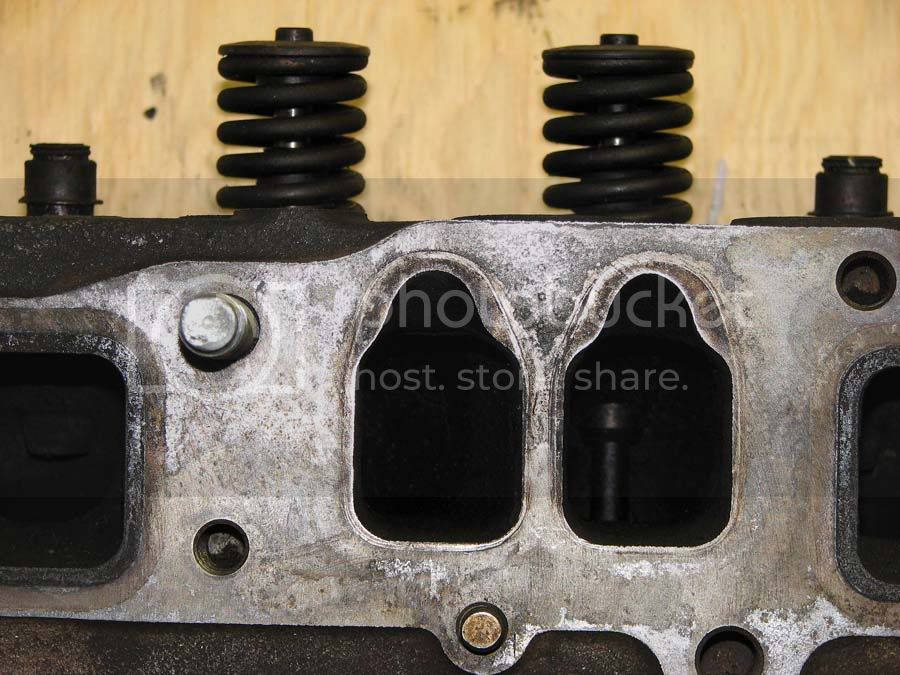
Shot of the uncleaned ports and manifold mating surface. Note (by reference to the position of the intake valve springs) the different geometries that the ports for 1/6, 2/5, and 3/4 have. 2/5 run in to the combustion chambers at pretty much a right angle, 3/4 have a bit of an angle, and 1/6 have a significant angle. This will impact where around the intake valve (relative to the combustion chamber clearances around it) most of the flow will enter the cylinder. 1/6 should have an advantage in terms of flow all other things being equal. (more on this later I suppose)
IMG_4113small.jpg

IMG_4112small.jpg

IMG_4111small.jpg


Shot of one of the chambers (#2 in this case) to show the built up carbon/crap. Must have had a decent impact on compression ratio and cylinder pressure. Anyone up for running some sea foam/ATF/misted water through their engines?
IMG_4096small.jpg


Hmm, looks like someone knew what they were doing, or maybe this is why the truck this came out of was taken on for an engine swap? (link for anyone who doesn’t know what I’m referring to: https://forum.ih8mud.com/60-series-wagons/113830-what-well-whatever-its-leaking.html)
IMG_4128small.jpg
 
Last edited:
Pics of the torn-down head and valves.

Example of ports/valve pockets in one of the chambers.
IMG_4126small.jpg


The valves (intake left, exhaust right) as they came out, and after an introduction to the scraper and wire brush.
IMG_4146small.jpg

IMG_4140small.jpg

IMG_4145small.jpg


Typical thick caking of crap on one of the intake valves.
IMG_4141small.jpg


Carbon build up on the back of an exhaust valve.
IMG_4142small.jpg


Cause for concern? The hardened outer shell of the stem on the exhaust valves appears to be burned below the level of the valve guide and bits of it can be chipped off with a fingernail. I would assume that this renders the ex. valves junk, can’t imagine bits of steel dropping into the cylinders is a good thing. Opinions on this?
IMG_4147small.jpg
 
The unmolested AFM (well, unclothed I suppose).

View with the bottom plate removed. You can see the idle air bypass on the right. Despite the resistance imposed by the spring action of the vane, I’ve read that the vane type AFM is actually less restrictive than a hot wire MAF sensor. Hopefully we can improve things a bit yet.
IMG_4162small.jpg


View down into the brainy bits of the AFM. I thought I would have to pop the black plastic cap and disengage the vane’s pivot shaft to release the bottom plate, but it turns out the shaft doesn’t engage the bottom plate, so no need to do this. (kind of neat to see the inner workings though.
IMG_4161small.jpg


View of the intake end of the AFM, showing where there is a sharp, non-streamlined edge where the main body and base plate meet. This will get some attention….
IMG_4155small.jpg

IMG_4154small.jpg


View of the same feature from the bottom, with the base plate removed.
IMG_4164small.jpg


View of the outlet end of the AFM showing a non-streamlined transition from the squared-off cross-section of the AFM to the rounded cross-section of the intake hose (idle air bypass on the left). There is also another sharp edge where the main body and base plate meet.
IMG_4156small.jpg


View of the sharp edge from below with the base plate removed.
IMG_4166small.jpg


There are other minor features that could be smoothed down, but this covers the obvious ones. I should point out that modifying things upstream and down stream of the vane shouldn’t have any effects on the performance of the AFM, but you don’t want to mess around with the vane itself, or the wall/ceiling/floor along its travel, as that could throw it out of whack.
 
Last edited:
Wow, thanks for taking the time to post all that. Im looking forward to seeing how you rig up a flowbench.
 
If you're thinking to fill in & blend places like those odd little spots on the AFM have a look at Devcon Aluminum Putty. It is an epoxy with aluminum dust in the mixture. Once set up the difference between the base metal and the epoxy when grinding etc. is not very noticeable. It is very good for adding 'metal' to aluminum parts without welding when doing contouring type work.
 
Im looking forward to seeing how you rig up a flowbench.

So am I :hmm:


Uh oh, now I better really do something.

If you're thinking to fill in & blend places like those odd little spots on the AFM have a look at Devcon Aluminum Putty. It is an epoxy with aluminum dust in the mixture. Once set up the difference between the base metal and the epoxy when grinding etc. is not very noticeable. It is very good for adding 'metal' to aluminum parts without welding when doing contouring type work.

I was going to ask what would be good to use. Thanks for reading my mind. :cheers:
 
Wow, thanks for taking the time to post all that. Im looking forward to seeing how you rig up a flowbench.
Did a qwik search and found this: Flowbench Technology
I recall reading about a guy building one that used his shop-vac though I don't recall any details of it.

If you want plans etc: Mercdog Motorsports - About 68 Flowbench

I'm not sure that it's worth the software. Seems like putting the test points in Excel and graphing from there would be simple enough.

Thanks again. Mine is going to be a vacuum cleaner and manometer special, but it will certainly help to have a look at how others are doing it.
 
Just called the machinist, the head is good. :) I'll pick that up this afternoon.

Should be getting some moulds made in the next couple days.
 
I don't know a whole lot about flow benches beyond what I can guess about them, but it seems to me that as long as you have something to generate a consistent vacuum and the means to measure the pressure drop across a flow restriction then everything else is gravy.

What a very unknown to the general populace, but well known in certain road racing circles cylinder head guy told me was that the secret is in the low-lift flow. The valve spends more time at or above, say .025" off the seat than it does at .500" off the seat. Made sense to me.
 
That brings up a good question (and one I have unsuccessfully tried to get an answer for). What is stock valve lift with a 2F/3F cam? I've seen ~0.43" for one after-market cam, but never a figure for the stock cam. The witness marks on the valves I pulled seemed to suggest a greater lift, but this could be from some valve float? Or maybe the engine the head was pulled from even had a high-lift cam?

On a somewhat related note, is it typical to cut the length of the push rods an amount equal to the shaving of the head to retain full travel of the springs?
 
No idea on the stock lift number. You may have to set up & measure it to know for sure.

The most common reason to adjust push-rod length is to get the proper rocker geometry so it isn't pushing the stem tip sideways and wiping out the valve guides. Shaving the head would upset this relationship, but I can't say that I've seen many people address this. At least they have not mentioned it in their posts. Note that most of my observation & experience is respective to U.S. V8's.
 
Last edited:
Great write up Doc. I will forward pics of the TB and the injectors as soon as I have them on the bench. Injectors are out for service and flow rating of which will supply you numbers for that. TB is on my bench soaking in cleaner and will begin to tear down over the holiday weekend. Also take your intake to a powder blaster and tell them to have a good once over of the internals. It will really makes it baby but smooth!! Keep up the great thread and I am glad you choose me to participate in a small way!
 
Great write up Doc. I will forward pics of the TB and the injectors as soon as I have them on the bench. Injectors are out for service and flow rating of which will supply you numbers for that. TB is on my bench soaking in cleaner and will begin to tear down over the holiday weekend. Also take your intake to a powder blaster and tell them to have a good once over of the internals. It will really makes it baby but smooth!! Keep up the great thread and I am glad you choose me to participate in a small way!

Thanks for taking part, trust me, this could turn into a real gong-show yet. Take your own good time on the TB, it's going to be a while before the I start cutting metal at this end.

Thanks for the tip on the powder blasting. I'm going to have to start up a sheet with all of them.

blast intake manifold
Devcon aluminum putty
bead blast the head
....


Picked up the head and intake, all nice and wrapped up for now. I'll likely take them in to the lab with me tonight to get some good pics and measure all the chamber volumes. Picked up a cheap die grinder (for $10 it'll make a fine paper-weight if it's crap) and a couple basic carbide burrs too, I'll have to do some internet shopping to find some more refined shapes, and longer shanks. If the whole thing goes well, maybe I should make the die grinder into a hood ornament or some under-hood decoration.
 
Jesus RockDoc, you sure are going to town. There is an add in the classifieds section selling the tcase, trany, and 3FE engine for $500 if you need more cheap parts. He's in Canada otherwise i would've hoarded the spare parts myself.

If you need help designing or building a flow bench I can ask the engineers at my work. They do this kind of stuff for aerospace industry and I'm always asking them crazy questions like this.

good luck.
 
Jesus RockDoc, you sure are going to town. There is an add in the classifieds section selling the tcase, trany, and 3FE engine for $500 if you need more cheap parts. He's in Canada otherwise i would've hoarded the spare parts myself.

If you need help designing or building a flow bench I can ask the engineers at my work. They do this kind of stuff for aerospace industry and I'm always asking them crazy questions like this. Besides, the next block will be a 2F (I hope), or maybe a diesel.........

good luck.

Yah, I saw that classified. Unfortunately he's about 12 hours away, and I'm renting an old house with a couple other students, so I really don't have the space to store it.

I'm going to have to learn what I can about flow benches over the next couple of days, I'm sure I'll have some questions after that.
 
Last edited:

Users who are viewing this thread

Back
Top Bottom