
Box Rocket
SILVER Star
I don't often do instructional threads but I'm gonna give it a try here. Hopefully this will make sense. I used a few other threads about rebuilding the steering box rebuild as a reference for doing this upgrade and those other threads helped a lot. The only real difference I'll have here is the addition of the 105 sector shaft.
The parts to do the upgrade can be sourced a few different places, but Cruiser Outfitters, and Wits End both stock the parts and have "kits" with the parts and seal kits. There might be others out there too, and of course dealer parts counters should be able to get you all the parts also.
I got mine from Cruiser Outfitters since they are local and I could pick it up at the shop.
The parts you will need for the 105 sector shaft upgrade are:
-105 Sector shaft
-105 pitman arm
-new pitman arm nut and split washer
-new sector shaft stake nut and adjustment screw
-steering box seal and o-ring kit
-ATF or power steering fluid
-moly grease
Tools needed:
-Flat Screwdriver
-17mm wrench
-14mm socket
-32mm socket
-10mm allen wrench
-snap ring plyers
-dead blow mallet
-Adjustment screw stake nut SST (I'll show you what I used later in the thread)
DISASSEMBLY
I was using a spare steering box that I had on the shelf, but if you don't have a spare box you'll need to remove your steering box from the truck. Obviously.
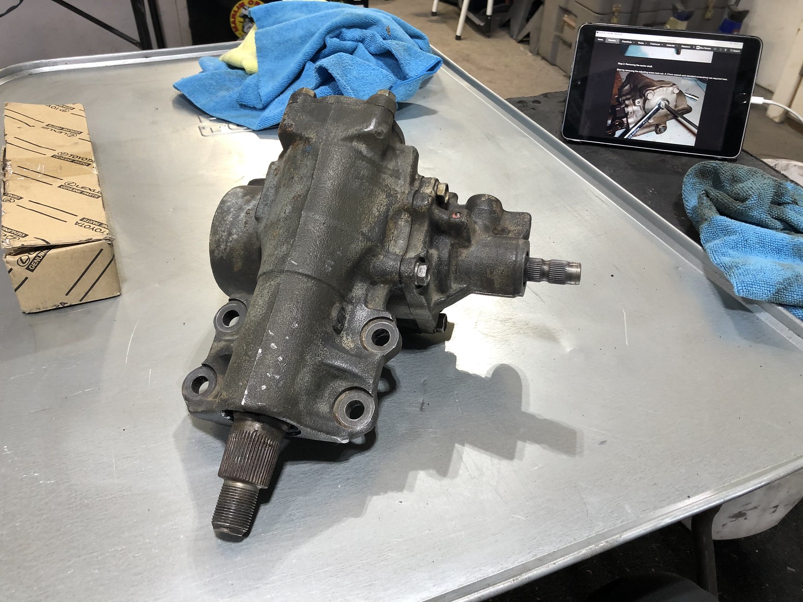
Step 1: Once you have the steering box out of the truck and on the bench you need to remove the pitman arm. The pitman arm nut is a 32mm nut so you'll need that size socket if you don't have one already. At a minimum you'll need a pitman arm puller. Depending on the condition of your box and arm you may need a press to get the pitman arm off.
 Steering box FZJ80 by Adam Tolman, on Flickr
Step 2: Remove the sector shaft. To do this you need a flathead screwdriver and a 17mm wrench. Remove the adjustment screw lock nut using the screwdriver to make sure the adjustment screw doesn't spin.
Steering box FZJ80 by Adam Tolman, on Flickr
There's a seal washer under the nut. Your new seal kit hopefully includes a new seal washer. If it doesn't, you'll need to reuse this one if it's in decent shape so don't lose it. You'll reuse the nut.
Steering box FZJ80 by Adam Tolman, on Flickr
Next you need to remove the side cover. There are four 14mm bolts that hold the side cover on. Remove the 4 bolts.
Steering box FZJ80 by Adam Tolman, on Flickr
Once the bolts are removed, tighten the adjustment screw with the screwdriver and it will push the side cover out.
Steering box FZJ80 by Adam Tolman, on Flickr
Steering box FZJ80 by Adam Tolman, on Flickr
The side cover has an o-ring that will get replaced and there are needle bearings inside. Typically these don't need to be replaced but make sure yours are rolling smoothly and replace if needed. I didn't need to replace the bearing.
Steering box FZJ80 by Adam Tolman, on Flickr
With the side cover removed you can tap the sector shaft out of the box with a dead blow. It should come out with a few light taps.
Steering box FZJ80 by Adam Tolman, on Flickr
Steering box FZJ80 by Adam Tolman, on Flickr
Here's the stock 80 sector shaft next to the 105 shaft. There's a noticeable difference in size as well as spline count. Note: the splines on the 80 shaft look to have a slight twist starting. If the splines on your sector shaft have any amount of twist to them, the shaft should be replaced. Twisted splines are a warning that the shaft is close to failure. Unfortunately the only way to really check the splines for twisting is to remove the pitman arm. Sometimes you can see some twist in the splines without removing the pitman arm by holding a straight edge up to the box and check the splines against the straight edge. Also note in this photo: the steering box seal kit with part number.
Steering box FZJ80 by Adam Tolman, on Flickr
The twist in the splines is more visible in this photo. The twist will nearly always be right at the top edge of where the pitman arm sits on the splines.
Steering box by Adam Tolman, on Flickr
Time to move to the next step.
The parts to do the upgrade can be sourced a few different places, but Cruiser Outfitters, and Wits End both stock the parts and have "kits" with the parts and seal kits. There might be others out there too, and of course dealer parts counters should be able to get you all the parts also.
I got mine from Cruiser Outfitters since they are local and I could pick it up at the shop.
The parts you will need for the 105 sector shaft upgrade are:
-105 Sector shaft
-105 pitman arm
-new pitman arm nut and split washer
-new sector shaft stake nut and adjustment screw
-steering box seal and o-ring kit
-ATF or power steering fluid
-moly grease
Tools needed:
-Flat Screwdriver
-17mm wrench
-14mm socket
-32mm socket
-10mm allen wrench
-snap ring plyers
-dead blow mallet
-Adjustment screw stake nut SST (I'll show you what I used later in the thread)
DISASSEMBLY
I was using a spare steering box that I had on the shelf, but if you don't have a spare box you'll need to remove your steering box from the truck. Obviously.
Step 1: Once you have the steering box out of the truck and on the bench you need to remove the pitman arm. The pitman arm nut is a 32mm nut so you'll need that size socket if you don't have one already. At a minimum you'll need a pitman arm puller. Depending on the condition of your box and arm you may need a press to get the pitman arm off.
 Steering box FZJ80 by Adam Tolman, on Flickr
Step 2: Remove the sector shaft. To do this you need a flathead screwdriver and a 17mm wrench. Remove the adjustment screw lock nut using the screwdriver to make sure the adjustment screw doesn't spin.
 Steering box FZJ80 by Adam Tolman, on Flickr
There's a seal washer under the nut. Your new seal kit hopefully includes a new seal washer. If it doesn't, you'll need to reuse this one if it's in decent shape so don't lose it. You'll reuse the nut.
 Steering box FZJ80 by Adam Tolman, on Flickr
Next you need to remove the side cover. There are four 14mm bolts that hold the side cover on. Remove the 4 bolts.
 Steering box FZJ80 by Adam Tolman, on Flickr
Once the bolts are removed, tighten the adjustment screw with the screwdriver and it will push the side cover out.
 Steering box FZJ80 by Adam Tolman, on Flickr
 Steering box FZJ80 by Adam Tolman, on Flickr
The side cover has an o-ring that will get replaced and there are needle bearings inside. Typically these don't need to be replaced but make sure yours are rolling smoothly and replace if needed. I didn't need to replace the bearing.
 Steering box FZJ80 by Adam Tolman, on Flickr
With the side cover removed you can tap the sector shaft out of the box with a dead blow. It should come out with a few light taps.
 Steering box FZJ80 by Adam Tolman, on Flickr
 Steering box FZJ80 by Adam Tolman, on Flickr
Here's the stock 80 sector shaft next to the 105 shaft. There's a noticeable difference in size as well as spline count. Note: the splines on the 80 shaft look to have a slight twist starting. If the splines on your sector shaft have any amount of twist to them, the shaft should be replaced. Twisted splines are a warning that the shaft is close to failure. Unfortunately the only way to really check the splines for twisting is to remove the pitman arm. Sometimes you can see some twist in the splines without removing the pitman arm by holding a straight edge up to the box and check the splines against the straight edge. Also note in this photo: the steering box seal kit with part number.
 Steering box FZJ80 by Adam Tolman, on Flickr
The twist in the splines is more visible in this photo. The twist will nearly always be right at the top edge of where the pitman arm sits on the splines.
 Steering box by Adam Tolman, on Flickr
Time to move to the next step.
 Steering box FZJ80
 Steering box FZJ80
 Steering box FZJ80
 Steering box FZJ80
 Steering box FZJ80
 Steering box FZJ80
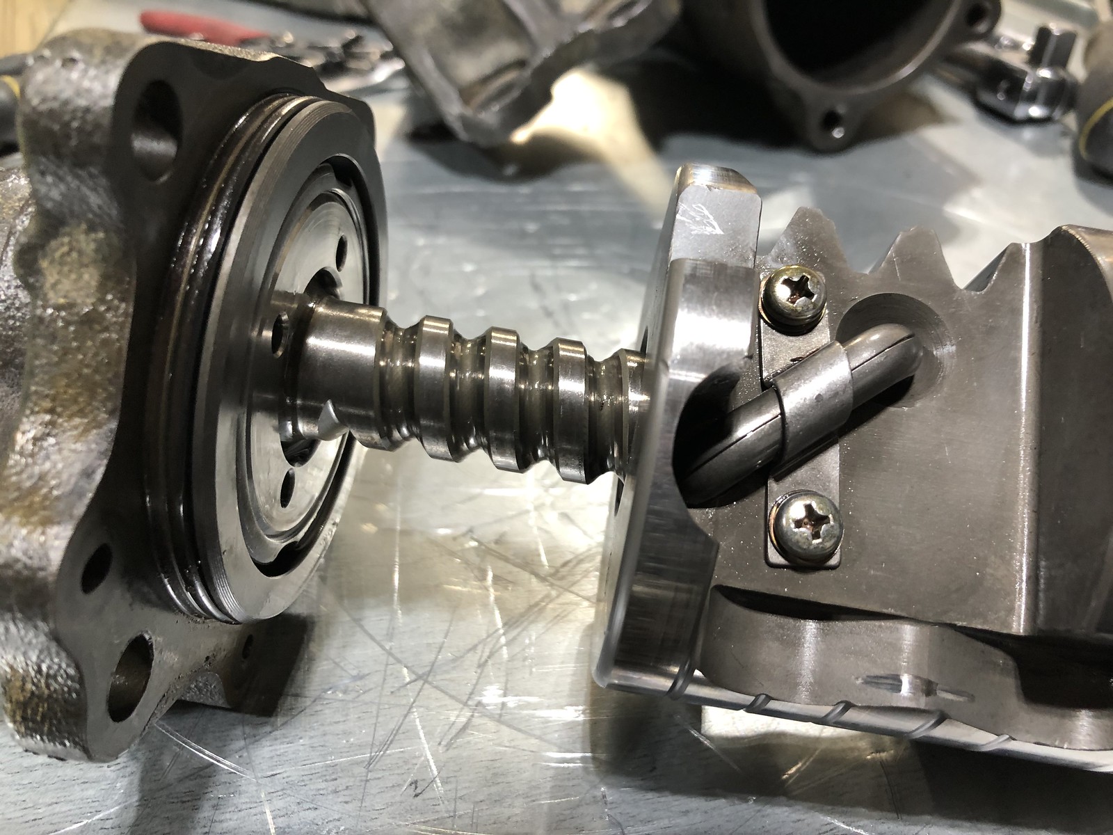 Steering box FZJ80
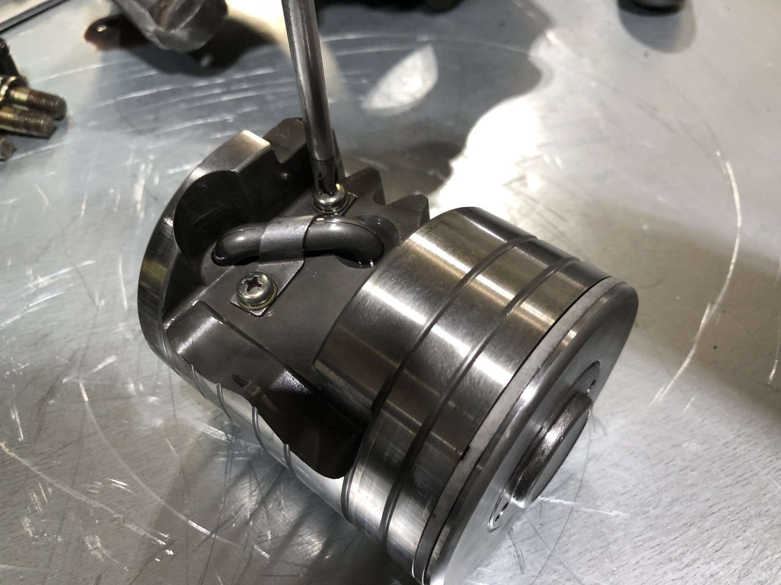 Steering box FZJ80
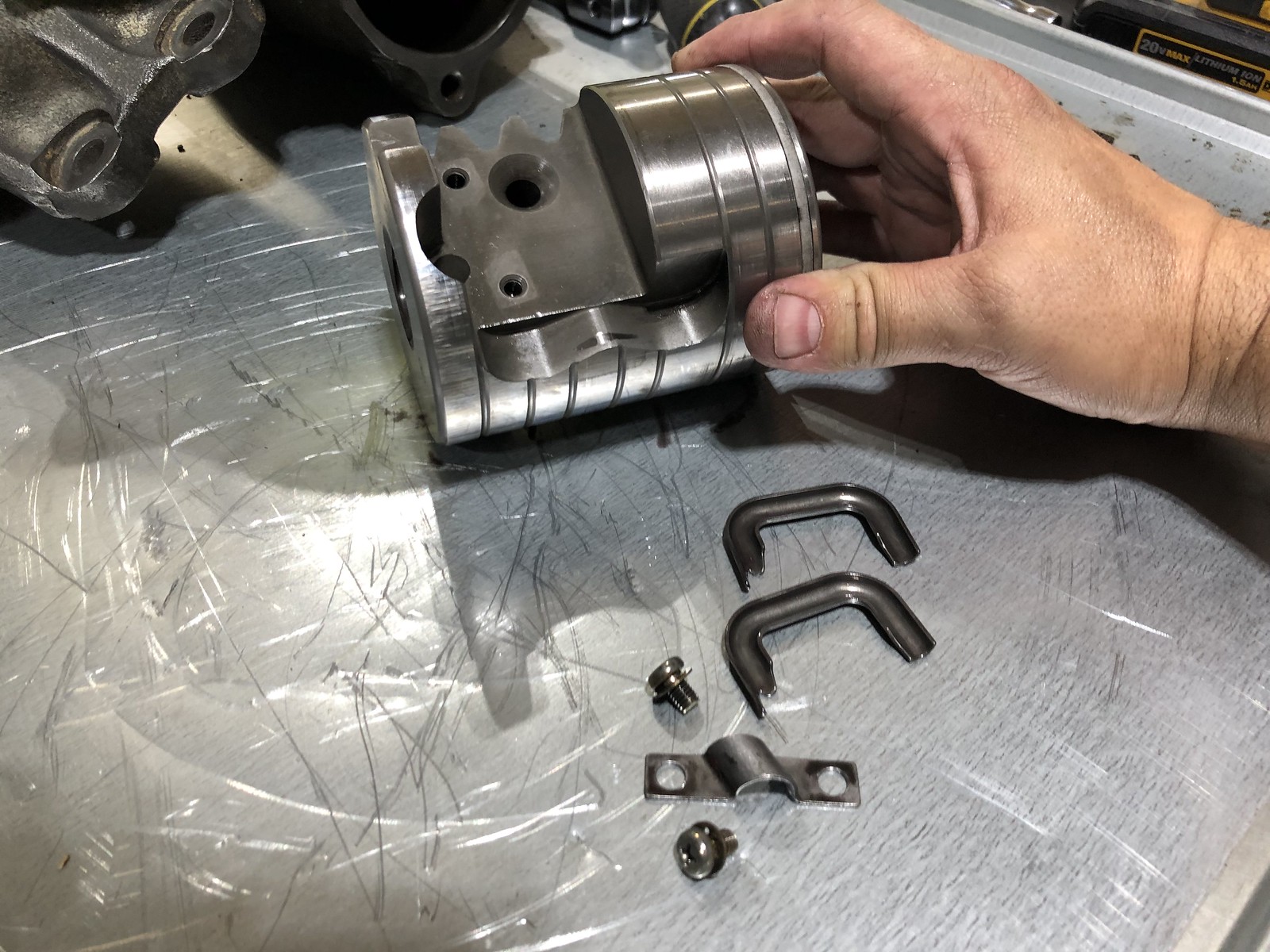 Steering box FZJ80
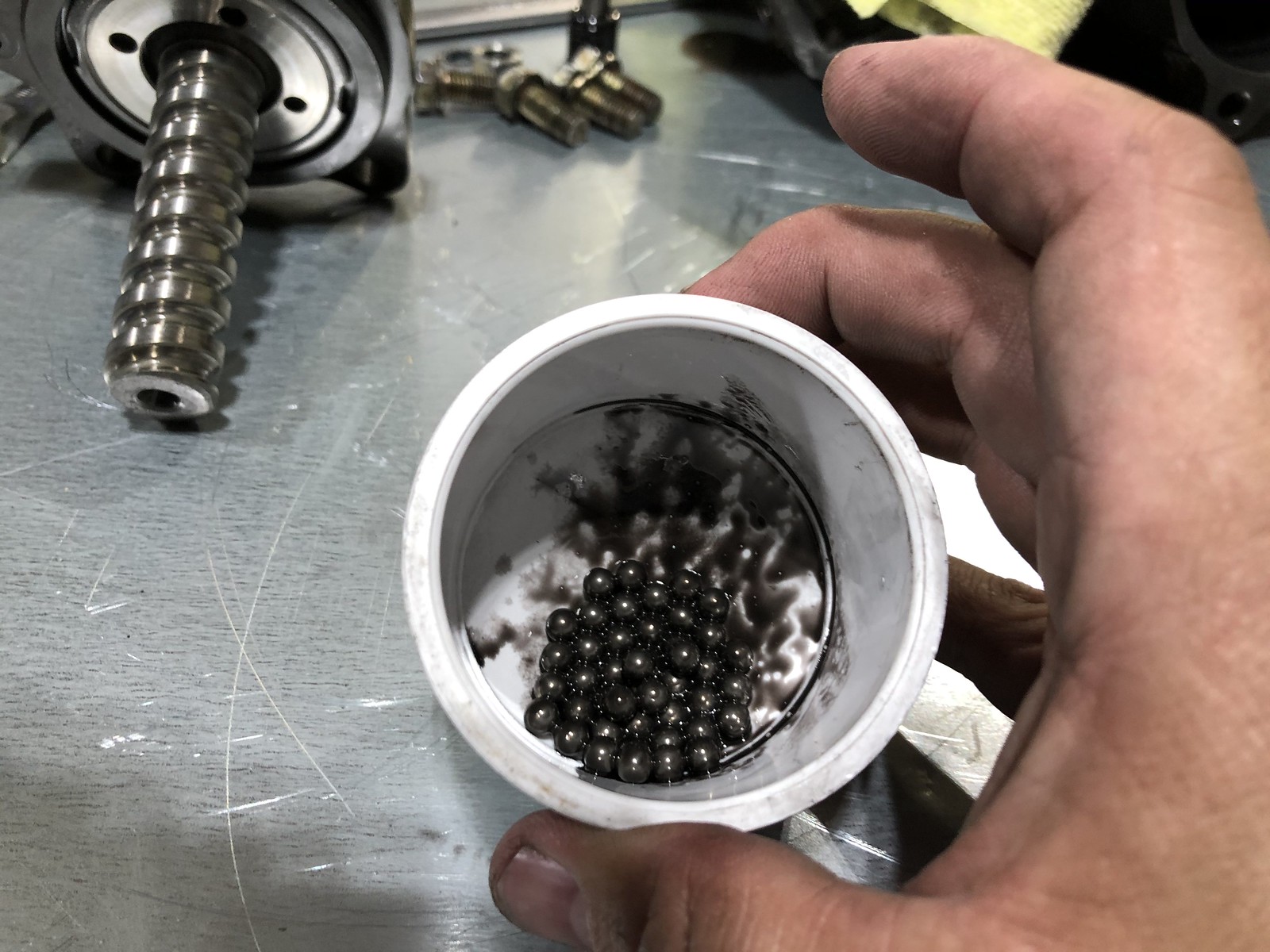 Steering box FZJ80
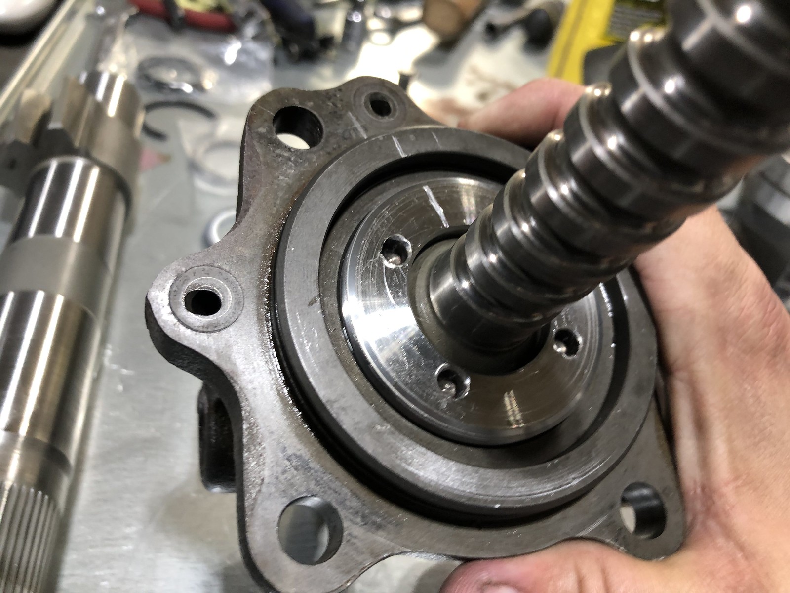 Steering box FZJ80
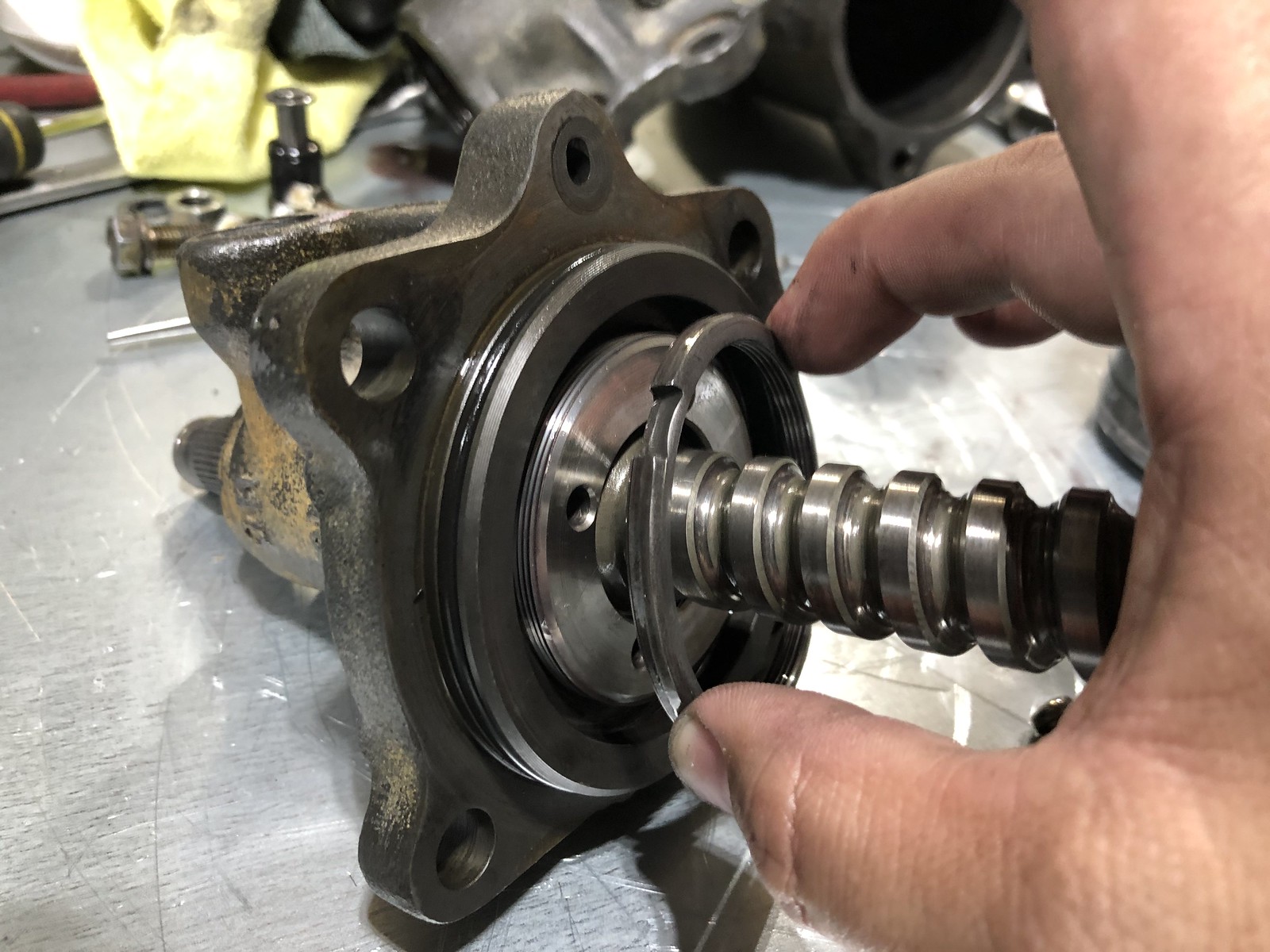 Steering box FZJ80
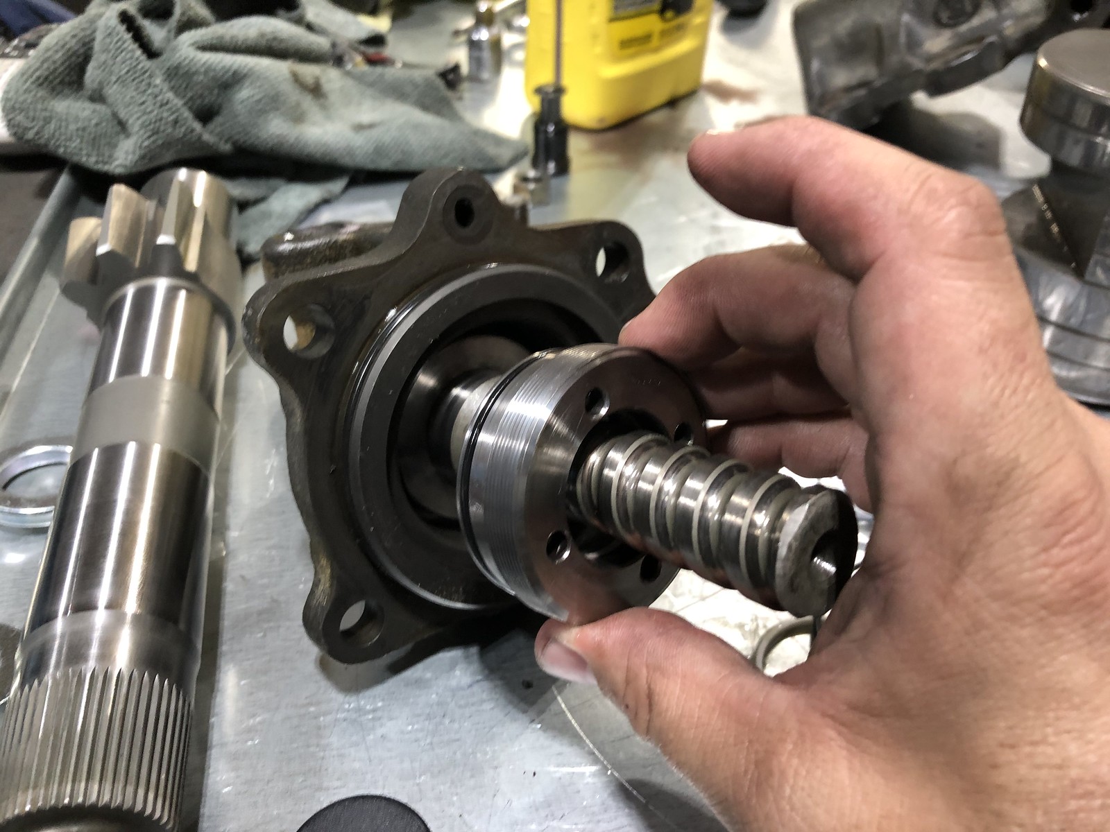 Steering box FZJ80
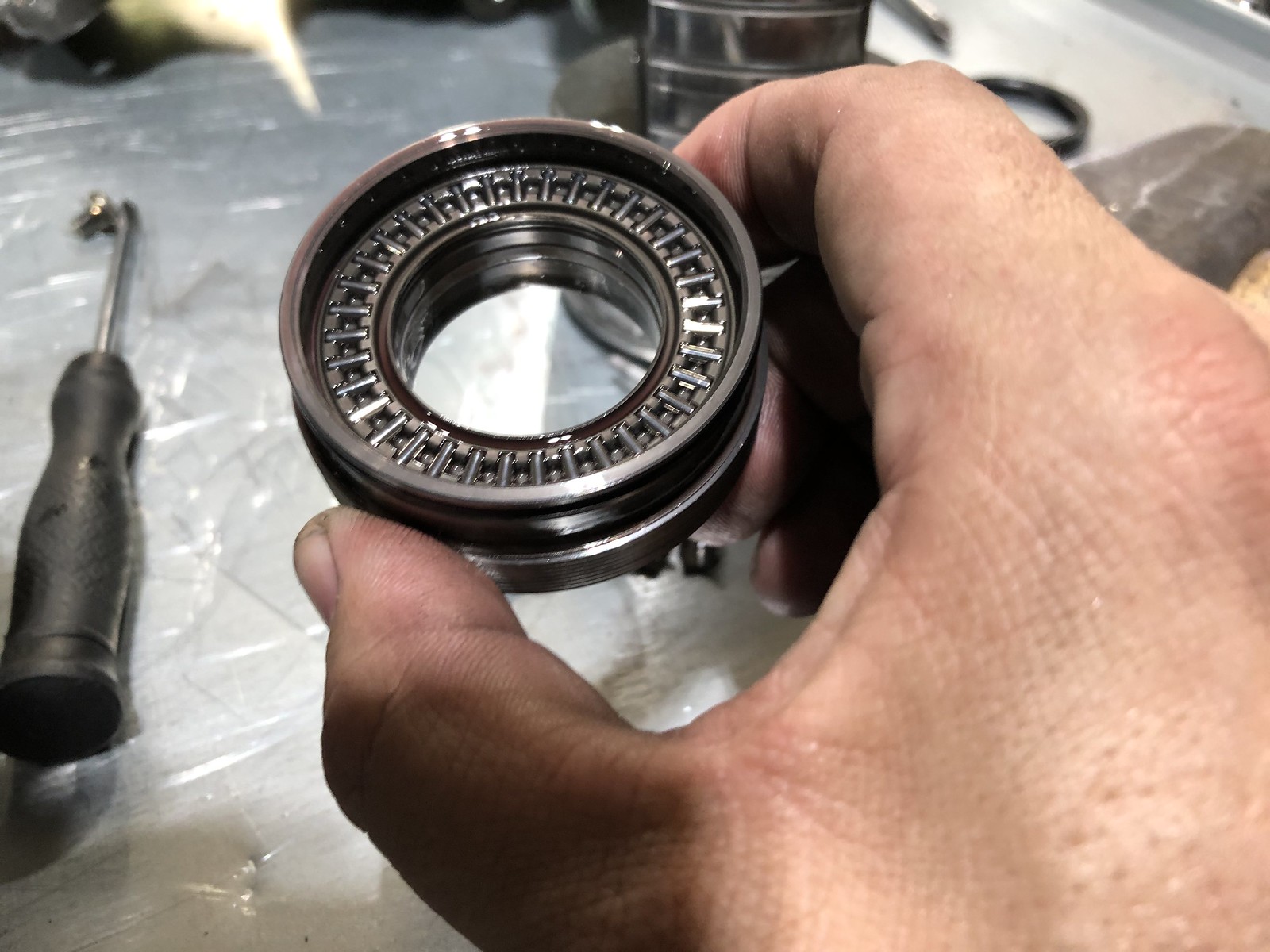 Steering box FZJ80
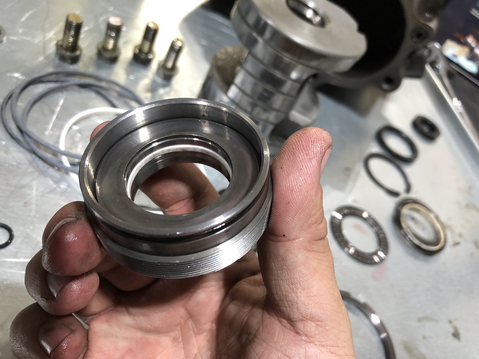 Steering box FZJ80
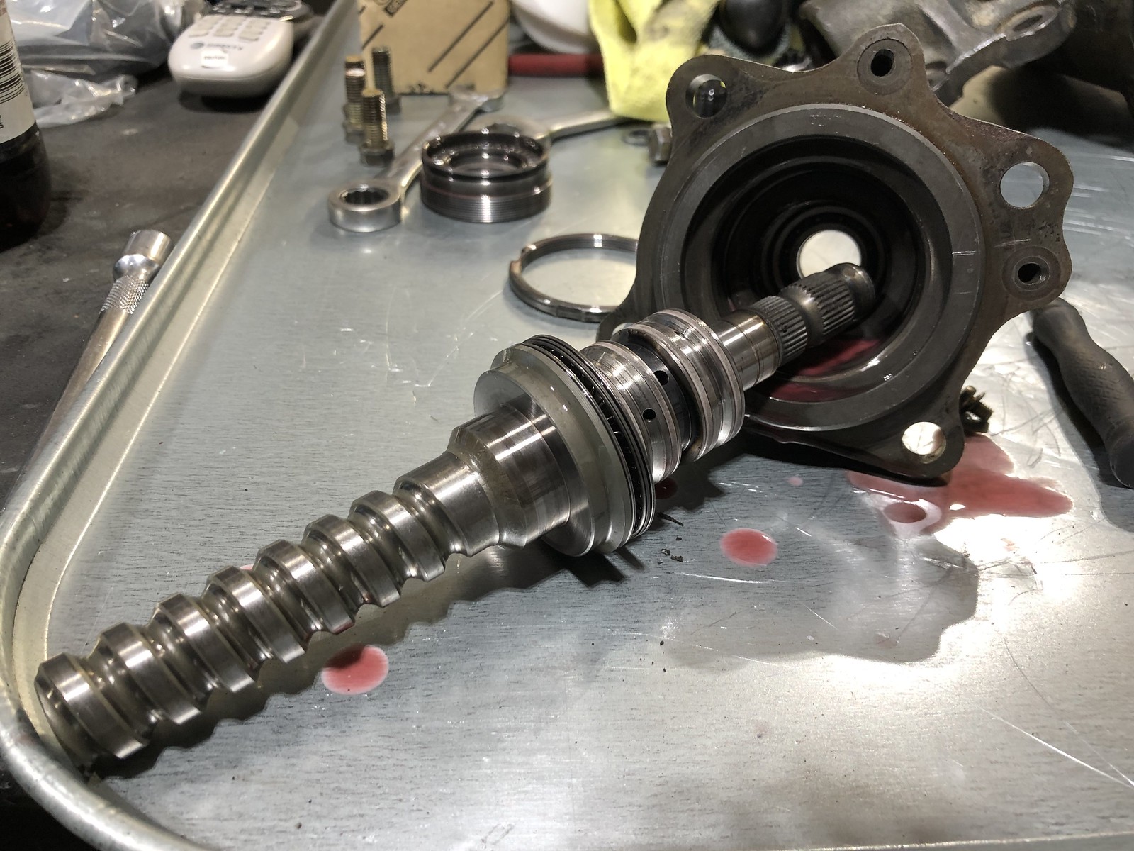 Steering box FZJ80
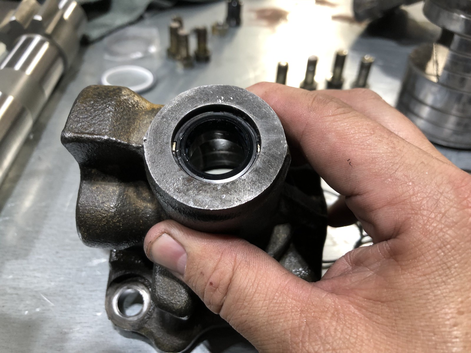 Steering box FZJ80
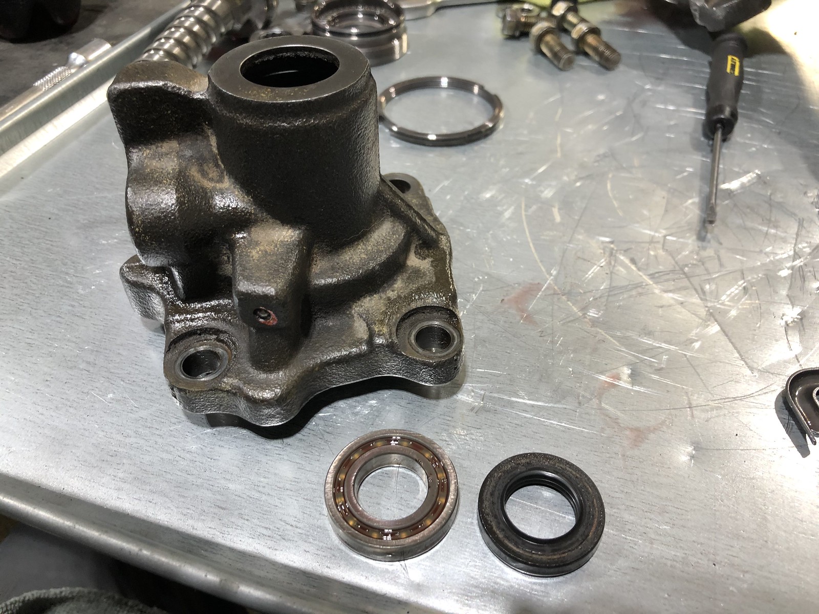 Steering box FZJ80
 Steering box FZJ80
 Steering box FZJ80
 Steering box FZJ80
 Steering box FZJ80
 Steering box FZJ80
 Steering box FZJ80
 Steering box FZJ80
 Steering box FZJ80
 Steering box FZJ80
 Steering box FZJ80
 Steering box FZJ80
 Steering box
 Steering box
 Steering box
 Steering box
 Steering box
 Steering box
 Steering box
 Steering box
 Steering box
 Steering box
 Steering box
 Steering box