Builds V8 (SBC) to V8 (Gen III Vortec) swap in my FJ60... (1 Viewer)

This site may earn a commission from merchant affiliate
links, including eBay, Amazon, Skimlinks, and others.

Nah, probably not. But, I'm not sure I've seen you use the angry foot before though...maybe the mildly annoyed foot, or the the slightly perturbed foot....but never the angry foot. Thought I might see it when your carb was giving you grief, but you kept your cool (mostly )...

Haha...you're right...and once this engine is in, hopefully this rig will never get my blood boiling like before!

...

Update time: Progress has been made...

11--swap-parts.jpg


Parts showed up...fancy stainless steel manifolds, and "universal" LS swap engine mounts.

Got the wire harness "done", for now:
12--wire-harness-done.jpg


The PCM will be located on the drivers side fender, and you can see all of the labeled connections there (fuel pump output, tach output, MIL lamp, OBD-2 plug output, e-fan output, etc...).

The lower left of the pic is the rear O2 sensors and VSS plug. Using a Dakota Digital adapter to provide the PCM will speed input - Hopefully it fits on the splitcase (goes onto the OEM speedo cable).

Top center of the pic is where it bolts to the intake manifold and splits off in the proper direction, to go to each sensor and plug. If you look carefully, there is a bundle of pink wires...those all need to go to the fusebox for +12v input. That work will come once the engine is set permanently in place.

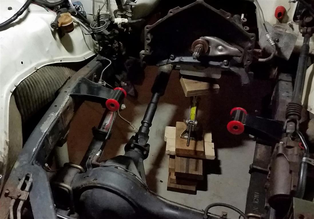
Speaking of which...

Yesterday, I got out of work early and got the engine off the pallet it was shipped on, and set between the frame rails!

13--vortec-test-fit.jpg

Here's a shot from the front, as I was checking hood clearance.

Looks like I have about an inch to work with, above the motor:

14--hood-clearance.jpg


Also checked the fit of the transmission input shaft to the pilot bearing...all looks good there:
15--trans-mated-to-engine.jpg


...

So it will sit here a while I work on the motor mounts...then I'll pull it back out, clean the motor up a little, install the clutch and flywheel, and stab it back in for good.

Then it's custom exhaust (the manifolds fit great in my particular application), fuel system, intake piping, finish the wiring, etc, etc...

But I'm just over 2 weeks in at this point...making most of my progress each evening, 30-45 minutes at a time. Plus a 1-2hr block here and there on the weekends. I'd guess I have 12-13hrs total into it at this point.

Anyway, I'll post more as there is more to post!

- Brian
 
Made no real progress on the swap in the last couple days - I've been cleaning up under the hood, in preparation of future work.

The previous V8 swap was done "OK", but stuff like the smog and carb fan wiring/plugs were all left on the drivers side fender...looked half-assed.

So I'm stripping back the harness, removing all those un-needed wires and plugs...and I'll re-wrap the whole shebang once I put the PCM in place and run those new wires along with the old (through the grommet, and into the cab).

Trying to think ahead, and do this annoying clean-up work as I go...so when it's all said and done, it will be clean, easily serviceable, and "done right".

- Brian
 
Made a little progress over the weekend, and parts continue to show up.

Got the old motor mounts cut off, ground down, and I test fit the new ones:

Old (with crappy welds):
16--old-motor-mount.jpg


New, just test fitting:
20--motor-mount-test.jpg


Also made some progress on the VSS / cable speed sensor adapter. The Vortec PCM likes to see a speed signal input for fuel economy, and to prevent stalling (apparently - This is only from what I have read).

I bought a Dakota Digital unit (SEN-4160) that sandwiches between the stock speed sensor and the cable. BUT, the OEM cable end does not fit the DD adapter (as I expected). The sensor is for a GM trans, and uses a .100" x .100" (or so) square "dowel" to spin the sensor, then the stock cable plugs into the other side...so you retain the stock speedo functionality but you also get the 8k pulses per mile that the PCM is looking for.

To make it work on the transfer case side, I made a new "dowel" from an old antenna I had laying around. It's roughly 1/8" diameter, and stainless...so a perfect material to use. I just filed flats onto four sides of the VSS adapter end, and then put a 90-degree bend in the other end (and used a sleeve to center it) so it fits nicely into the Toyota speed sender unit.

Hard to describe with words, here's a pic:
17--vss-adapter.jpg


The flat bar at the top of the pic is the dowel they want you to use, just for reference.

The other side will not be as easy. The stock speedo cable terminates with a (rougly) 3/16" diameter end, with a "bump" to grab the center of the OEM sender.

I plan to grind/file this end down to engage the Dakota Digital VSS adapter...wish me luck:
18--vss-adapter.jpg


(OEM cable end on the left, and the provided dowel just put in there while I was brainstorming)

Additionally, my "pile of parts" continues to grow:

19--pile-of-parts.jpg


You don't realize on the front end how much $$$ you'll spend on $10-20 items to finish up a project like this.

Heater hose, heater hose T's and adapters, radiator hose, hose clamps, relays, split loom, extra wire and electrical tape, O2 sensor bungs, air intake pieces, fuel filters, etc...as well as the aforementioned EGR and EVAP plugs, etc, etc...

All necessary, but all cost $$$...and really add up. The "miscellaneous" line item in your swap budget should be bigger than you think, trust me!

...

Anyway, PCM is out for a retune right now. If I can get the motor mounts welded in soon...I'll really start making progress on getting it running (putting stuff back together, rather than taking stuff apart and ordering parts!).

- Brian
 
Subscribed :beer:
 
Subscribed and love the motor mounts.
 
yeah dude there are always those small things that end up costing lots. Any project manager will tell you that you should ALWAYS plan your budget then add 10-15% extra, especially when it comes to any type of construction remodel or restoration.
 
^^^ Wise words.

...

Made some more progress last week, and got the motor mounts welded in yesterday.

Started by getting the Toyota oil pressure sender adapted to work on the 4.8.

Took the factory GM oil pressure switch:
21--oil-pressure-sender-2.jpg

(stock photo from the web)

Cut off the top, drilled it out to 5/16" ID, and tapped it to 1/8 NPT (for the brass adapter, the stock sensor is 1/8 BSPT):

21--oil-pressure-sender.jpg


...and used a 45-degree brass adapter for clearance:

22--oil-pressure-sender-2.jpg


One less thing to do.

...

Turned my attention to the motor mounts yesterday...

Had to balance "Sunday time with the family" and "grinding and welding on the truck"...but somehow made it work, and got something done.

The mounts were "universal", so I cut them down to length, and tacked them in place once I had the motor where I wanted it.

Then I carefully pulled the motor to finish weld. Even with an empty engine bay, it's like you're doing yoga to get to where you need to weld!

But I got it done after the kids were in bed (and while Sunday night football was on - Go Jags!) :

23--motor-mounts-welded.jpg


Tonight I'll clean it up, and paint the bare steel and welds.

Although I'm really tempted to get the motor in there for good, I'm going to take my time and do some of the things that will make my life easier, going forward. Replace the heater hose T at the firewall (and flush out the heater core), connect new high pressure hose to the fuel hard lines, clean up some of the wiring on the pass. side fender...that kind of stuff.

Anyway...I'm getting there. Slowly but surely! Thanks for reading.

- Brian
 
You know, there's always something that derails your progress.

The other day I decided to replace my drivers side headlight - I found the back (glass) cracked right between the contacts when I was doing the wiring clean-up not long ago. Pretty simple, right? Of course, the screws were rusty, and the heads were stripped out (PO's attempt at replacing the light?). No big deal - I'll just pull the whole housing and access those little chrome bezel screws from the rear with a pair of pliers. Well, one of the 12mm bolts holding the housing on snapped right off. Drilled that out and re-tapped it, grabbed a new bolt from the parts bin, and I'm back in business. Finally got those little headlight bezel screws out, and replaced them with a tiny stainless bolt...job done.

Last night it was the clutch fork. Decided to pop it off to get the new throw out bearing installed...and found the old TOB was installed incorrectly, and one of the spring tabs was broken off as a result. Sigh.

New (Chevy) clutch fork can't be that much, $15-20 right? Nope! $65. Dammit.

There's a right way, and a wrong way, to put a TOB on the clutch fork...
Throwout Bearing Installation.jpg


...and the wrong way breaks the spring tab, and costs me $65.

OK, I'm done ranting. Back to our regularly scheduled build thread.

New part will be here in a week - I'll finish other odds and ends until it shows up.

- Brian
 
Progress, continued...

While waiting on parts, I've been doing some more wiring clean-up (there was a veritable rats nest of wiring behind my battery...A/C relay, ignition coil relay, fog light relay, extra +12v feed going to the power distribution block in the cab, starter relay, etc...).

Cleaned a lot of that up, removed the factory wiring that will be unused, and got it (somewhat) organized for my new underhood fusebox install.

Cut off the old heater hoses and re-did them with a new T, and new hoses (the old stuff wasn't too old, but was cheap-o parts store hose...and was noticeably swollen).

Also cleaned up and painted the valve covers (needed something under the hood to draw your eye from the 15-year old grime and such that I won't bother cleaning off the Vortec motor!...hehe)

Started the fuel system, too. I put the electric fuel pump in the obvious spot (pass. side frame rail, just forward of the tank). I used a piece of 1.5" x 1.5" aluminum angle iron for the mount (as it gives a little impact / rock protection to the bottom of the pump).

To mount it, I drilled 2 holes in the frame and popped in (2) M8x1.25 riv-nuts...seems really solid.

Then I cut the fuel (feed) hardline to connect the outlet of the pump:

25--fuel-system.jpg


Dropped the tank a few inches to access the fuel connections at the top, and replace all the rubber lines with 5/16" fuel injection hose (probably not 100% necessary, as it's the suction side of the pump + the return...but better safe than sorry. Also, the hose on there was likely original!).

Put a low-resistance fuel filter before the pump (Napa Gold 3002) to save the pump from trash (rust?) from the tank.

Mostly finished here, but prior to wiring:

26--fuel-system.jpg


Got it wired up last night, and I'm moving on to the clutch fork (showed up Saturday) so I can mock up the slave cylinder bracket and make adjustments...then I can drop the motor in for good.

...

And for an "IH8MUD" note: It seemed like everything I touched under the truck, while I was working on the fuel system, caused sand and dirt to rain down on me. I have pressure washed the undercarriage TWICE since the last time the truck was really muddy...and driven it in the rain a handful of times...and dirt STILL falls right in my face while I try to work. I got it before, but I really get it now. I. Hate. Mud.

That's all for now.

...

EDIT: For anyone keeping score, we're at week 6 of this project. I was hoping to be a little closer to done at this point, but life gets in the way. I expect the "to do list" to start having items crossed off, for good, very soon. Back on the road in a month? One can hope!

- Brian
 
Last edited:
Allright, small victory today...!

I was going to try and drop the motor in this weekend, now that I have the clutch slave bracket all sorted out (it needed some massaging to point the slave cylinder right at the clutch fork...more on this later)...but I realized that I had not yet figured out how to get the Toyota temp sender (for the dash gauge) into the Vortec head.

The issue: The Toyota sender is threaded M16x1.5, and the spare port on the Vortec motor (rear side of the pass. head) is M12x1.5. I had planned to drill and tap it to 16mm...but several problems there.

1) I don't have a 16x1.5 tap...or a drill bit to match.

B) I don't like the idea of drilling into the head of my "new" motor. If I screw that up, it's a big problem at this point in the swap.

So I got to thinking...if I can't resize the hole to M16x1.5, maybe I can "turn down" the sender and re-thread it. But I don't have a lathe!?!?!?!?!

However, I do have a drill press...and the sender is only an $8 part, so no huge risk in trying to resize it in a drill press, using a file!

Here's what I started with:

27--temp-sensor.jpg


I chucked it up in my rusty Harbor Freight drill press, and started to turn it down:

28--temp-sensor.jpg


The threads came right off, and it seemed to be working OK...so I kept going.

Turned it down to just under 12mm diameter:
29--temp-sensor.jpg

(I actually went a little farther than this, but did not remeasure)

Once I (carefully) got the die started, I slowly cut new threads...and wound up with:
30--temp-sensor.jpg

(the factory GM plug for the spare coolant hole is shown here, for comparison)

The threads were a little less "sharp", because I turned it down a hair too small (necessary to get the die started)...but it seals up tight!

And finally, the sender installed:
31--temp-sensor.jpg


Ever since I bought this rig, the dash gauge has been disconnected...so this was a must-do, IMO.

I'll read the actual coolant temp via the OBD-II port (from the PCM, and shown on my Scan Gauge)...but at least I'll have a readout on the dash, and it will tell me if something is starting to go bad (overheating).

Anyway, I was surprised I pulled it off...glad I was working with a metal as soft as brass!

...

Hopefully the motor goes in tomorrow.

- Brian
 
Necessity = Mother of invention, I like it!
 
Necessity = Mother of invention, I like it!

Thanks!

The 'necessity' here was simply my impatience...I really wanted the motor bolted into the chassis this weekend!

...and after a lot of wrestling with it, I got it done!

If you've ever put a motor into a chassis with a manual transmission...you know that sometimes it lines up *just right*, and slides in place easily. Other times, you have to get the angle perfect, and wiggle it the right way, and cross your fingers, and have a lucky rabbits foot in your pocket, etc...

Well, I had to fight with this one. Wiggle the motor on the hoist, get underneath and wiggle the trans, then adjust the angle of the motor, and wiggle some more...repeat for an hour...etc, etc...

The tip of the input shaft on the trans had to be perfectly aligned with the pilot bearing, at the same time the clutch splines lined up....and then, eventually, it's just slid right in place.

So while it took some time, and used up a bunch of my energy...it's in:

32--vortec-installed.jpg

(headers are installed as well)

33--vortec-installed.jpg


Lot's of clearance in all the important areas:

34--vortec-installed.jpg


Exhaust will come off here (pass. side), run under the oil pan....and merge with the drivers side...then through a 2.5" muffler (Magnaflow?), and out the back.

Next up: Finish the clutch linkage (get the rod just the right length between the slave cylinder and the clutch fork), start the exhaust, hook up the fuel lines / heater hoses / PS hoses...then move onto the
rest of the wiring + new underhood fusebox. Install radiator and SPAL electric fan. Also need to fab up my air intake (I have a 3.5" aluminum pipe + couplers and clamps...going to reuse the GM airbox, installed on the drivers side of the engine bay)...

...and then maybe I can try to start it!

- Brian
 
Small update:

I want to keep this swap 'stock looking', in some ways...including using the Silverado airbox. I decided to put it on the drivers side of the engine bay (opposite of stock on the Silverado, and opposite of the "usual way" with a Vortec swap...mostly because the alternator sticks out, and you have to go around it when doing it this way).

The battery and the fusebox I intend to install both occupy the same space I would need for the airbox anyway...

I started by trimming the airbox down, mostly taking off the bottom, and then some from the side. Then I made some aluminum brackets to hold the box in place.

Pics probably do a better job telling the story:

35--airbox-brackets.jpg

(brackets)

37--GM-airbox-installed.jpg

(final location)

36--GM-airbox-installed.jpg

(another angle)

...

The MAF + rubber tube *just barely* clear the radiator...but are low enough that the upper radiator hose should go right over them.

So at this point in my swap, why am I spending time hacking up the airbox? Well, it's a finishing touch / detail that I might be inclined to skip if I don't do it now!!! Would be a whole lot easier to just put a cone filter on there and go...but "do it right, or do it twice".

I'll trim the 3.5" intake tube tonight, mate it to the MAF (using the GM rubber bellows, or maybe a 3.5" / 45-degree coupler I bought)...and I'll have an air intake. One less thing to do.

- Brian
 
^^^ OK, so the airbox isn't working as well as planned, once the radiator and upper hose are in and tight. Bare minimum, it gets moved back an inch or so...worst case, I build a heat shield and run a cone filter. Ugh.

...

As for a quick update: Wiring.

One of the "unknowns", or at least the part I couldn't wrap my head around before starting this project...was what exactly was involved with "LSx swap" or "Vortec swap" wiring.

You read online that "you just strip it down to a standalone harness"...or "it only requires 3 wires to run!".

Having just done this, I'll clue you in: It's not that simple, but it's also not very hard.

The gist of it is:

1) You strip back the harness to eliminate all the un-needed wires...these are pulled from the PCM end, and will be removed, completely intact, from the harness. I think it's 40 wires or so.

2) Then you route a handful of wires off the PCM plugs and around the engine bay - These go to things like the OBD-II port you'll want to add in the cab, to a +12v source for PCM power, and switched wires to activate relays are run to the fusebox you'll need to add (stuff like the fuel pump trigger wire, and fan relays).

Pretty straightforward...and what I've done and shown so far.

3) The unaddressed item so far in this thread, is the fusebox / relays you need to add.

From your new fusebox, you'll need a relay to supply power to a bunch of fused wires...these power the sensors when the key is switched on / or engine is running.

All of these wires that require switched +12v are PINK (pretty standard on the GM / LS / Vortec swap wiring...pink requires switched +12v, and orange requires constant / battery +12v).

38--pink-harness-wires.jpg


All the pink wires are shown here, these were all cut off at the C100 connector of the wiring harness.

13 wires in total: One for each coil plug (2 total), one for the MAF (1), one for each O2 sensor (2 total), and then one for each injector (8 total). I used a multimeter to test continuity (beep test) to determine what wires went to what sensor/plug...then labeled them.

It appears that some people bundle these together and use only 2-3 fuses, but I'm going to use (5) total fuses...all powered by one relay. Should make future troubleshooting easier. The relay will give +12v when the key is in the on/run and start position. Power will go through the fuses as such:

1) Coils, paired together.
2) MAF
3) O2 sensors, paired together
4) Drivers side injectors
5) Pass side injectors

I've already extended and run the wires to the pass. side of the engine bay (right behind the battery).

For the injector wires, I went ahead and bundled them together (4 and 4, drivers side and pass. side), so there's only 2 larger gauge wires at the fusebox.

...

After typing that all out ^^^ ...it's not as simple as I intended it to look...but trust me, it's not that difficult. Once you have the harness in your hands, and if you use the wiring resources that are all over the web...you'll understand exactly what needs to happen. Don't let it scare you off!

I'll try to post a shot of my fusebox and maybe a wiring diagram later this week.

- Brian
 
OK, here we are, a full month later...and it's ALIVE...!

Well, it starts and idles. There's no exhaust and no radiator installed...but it turned over and fired off pretty quick!

I've spent the last month doing wiring, mostly. Aside from the PCM wiring and such, I've been redoing the alternator wires, starter wires, all the grounds, etc...everything under the hood.

Here's a shot, when I was halfway finished:
40--fusebox.jpg


It's a fusebox from a '95 Nissan 240SX...stripped down to 6 fuses and 6 relays...and then I added a new fusebox (6 more fuses) that power all the engine sensors (those pink wires I referred to above).

The whole fusebox is run through a 100A main fuse, fed directly off the battery.

Wires behind it still look sloppy here, it's cleaner now.

I also finished the air intake. I had bought a 3.5" dia / 90-degree aluminum tube to use, but the bend was too gradual (too close to the radiator)...so I had to switch to tighter radius couplers. Looks pretty good now, too:

39--intake-pipe.jpg


It's a 4" --> 3.5" reducer off the throttlebody, 3.5" dia 90, then a 3.5" dia 45 coupler going right into the GM rubber flex tube.

I hacked up the aluminum tube into 3" long straight sections, then "rolled a bead" into the tubing with a pair of wire cutters. It's solid, and should flow well, and not come apart.

...

The exhaust is just 90-degree mandrel bends to route the exhaust under the truck, right now.

Finishing the drivers side should be pretty simple...just straight back. The passenger side has to go back, up a little and past the transfer case (and t-case shifter)...then it will turn 90 towards the drivers side, go up and over the rear driveshaft, turn 90-degrees to the rear...into a Magnaflow Y-pipe to merge with the drivers side. Then out the back through a Magnaflow muffler.

...

Back to the engine actually RUNNING!

I'm not seeing oil pressure, but I have to think it's the sender or wiring. No weird noises or any indication there's no oil pressure - But that's numero uno on my list of thing to investigate (I have the FSM pages to reference) tonight.

The OBD-2 ports reads data, I'm seeing 14.3v from the alternator, and everything else seems to function as it should...really happy with the work I've put in, so far.

Also finished the throttle cable last night. It's super smooth compared to the Spectre universal setup that was semi-rigged on there before (with the carb). I used an OEM cable from a 240SX (noticing a pattern; 240SX parts? I had 11 of them over the last 15 years...projects and racecars...so I have lots of spare parts).

The radiator should be easy...the lower hose is a part I found on here (I'll list the # later)...and with a small amount of length trimmed off, it's *perfect*. The upper hose will be a little more complicated, but I have a couple ideas.

Anyway, I might be able to test drive it in a week or so...really anxious to get back to enjoying it!

Thanks for reading.

- Brian
 
On the oil pressure, which of the two connectors on the sender did you connect the wire to? It needs to be connected to the center, if you connect it to the spade fitting sticking out you will short your GAUGE, not the sender. I did the same thing awhile back.

The sender is grounded, right? No teflon tape on the threads or anything?

The new gauge is NLA for the 60's but is still available for 62's and it should fit into your gauge cluster just fine. @gregnash did this recently if I remember correctly.

Yup I did the swap recently and the 62 gauge is a direct fit. Actually like it a little better as it had a couple tick marks instead of just the white line then red.
 
I've been following along and have to say you're doing a good job making it all work. I put a 5.3 in my 55 and I'm thinking about redoing the pass. side exhaust to run back as you described. Right now mine runs under the front of the oil pan. Running it this way with a SUA limits the upwards travel quite a bit. Look forward to your progress.
 
On the oil pressure, which of the two connectors on the sender did you connect the wire to? It needs to be connected to the center, if you connect it to the spade fitting sticking out you will short your GAUGE, not the sender. I did the same thing awhile back.

The sender is grounded, right? No teflon tape on the threads or anything?

All good thoughts. Bad ground was the only thing I had time to checked for on Sunday...and it tested OK.

Turns out...I simply hooked up the wrong wire. When I was doing all the sensor wiring a few weeks back, I forgot the oil pressure sensor. I thought it came from the drivers side of the engine bay...so I took a look at the wires I had stripped back off the harness and pulled into the cabin...and there was a matching wire. Yellow, with 2 black stripes, and 1/4" wide gold hash marks every inch or so. Same as the other end (that connects to the sensor)...so I wired it up.

Well, I traced it last night...and it goes to the (now useless) emissions computer. The actual oil pressure sensor wire comes off the PASSENGER side wiring harness in the engine bay. Oops.

I had the 3 unused wires on that harness just laying out of the way, waiting to be capped and taped off once everything was complete and running. I just assumed the sensor wire came from the other side of the engine bay, found a matching wire, and connected it there.

I guess if that's my only wiring mistake in this whole project, I'll take it!

I've been following along and have to say you're doing a good job making it all work. I put a 5.3 in my 55 and I'm thinking about redoing the pass. side exhaust to run back as you described. Right now mine runs under the front of the oil pan. Running it this way with a SUA limits the upwards travel quite a bit. Look forward to your progress.

Thanks.

I planned to go under my oil pan originally, but there's too many things trying to occupy that same space as the suspension compresses.

My SBC exhaust was routed all the way down the pass. side (done with flex pipe [thumbs down] )...so I knew there was room. Hopefully it's not too much of a nightmare trying to piece together the bends I needs to clear everything!

- Brian
 

Users who are viewing this thread

Back
Top Bottom