Builds Project F u k u s h i m a... my 1990 HZJ73 build thread (11 Viewers)

This site may earn a commission from merchant affiliate
links, including eBay, Amazon, Skimlinks, and others.

This weekends projects were rebuilding the rear drive shaft and starting to install the new Isspro gauges. It's kind of neat when you find something cool in a truck that came from the other side of the planet. I found these docs stuffed in between the stereo head unit and the storage bin below the stereo. I used google translate and it appears they are insurance docs of some sort.

IMG_3874_zpskvexqegd.jpg


When I removed the rear drive shaft last time I noticed that the diff side u-joint had a worn spot where the bearings would bind. I didn't notice and drive shaft vibrations, but after changing the u-joints I now can tell that there were vibrations and now it smooth as silk.

IMG_3881_zpseoga9cnm.jpg


IMG_3883_zpsqo6a8vpr.jpg


I also started to install the new gauges (egt, boost and trans temp). I drilled and tapped the intake crossover for the boost sensor.

IMG_3855_zpseuxeusde.jpg


IMG_3864_zpswamrjeht.jpg


Wrapped the boost sensor wiring harness and routed it into the cab through a grommet in the firewall.

IMG_3867_zps46v9ag5x.jpg


I also installed the thermocouple pre-turbo. The Safari turbo flange has a pre-drilled and tapped egt port for the thermocouple. I ran the wiring harness along the inner fender then through the same firewall grommet as the boost sensor.

IMG_3868_zpsh27vhbqx.jpg


IMG_3869_zpsojz3q81l.jpg


Then I started pulling stuff out of the dash in order to get ready for the gauge pod installation. The gauge pod hood that I ordered should be here this so I can start playing with the gauge mounts.

IMG_3872_zpsea5nenoh.jpg


Temporary gauge pod... LOL! Gauges work perfect... wired directly to 24v.

IMG_3877_zpsyuidx9ic.jpg


After getting the gauges installed I took the truck for a drive. They worked perfectly. I never got past about 800F and the boost never got over 10psi.

So... I decided to remove this and turn up the fuel...

IMG_3876_zpswirnrd6f.jpg
 
Look what arrived today... ordered it on Friday from Partsouq.com in Dubai and landed at my doorstep on Tuesday. Everything I've ordered from them is super fast and the prices are great. Now to start mocking up the gauge faceplate and mounting brackets.

IMG_3886_zpsu4boi2xw.jpg

IMG_3887_zpsf6kdsji4.jpg

IMG_3888_zpsgjnbuoaj.jpg

IMG_3889_zpsfzimntlx.jpg
 
Spent a few minutes mocking up the faceplate template. I will eventually cut this out of steel.

IMG_3904_zpsloynir7f.jpg


I used a 2" hole saw to cut the holes. Then stuffed the gauges in and this is what it will look like.

IMG_3905_zps3rsw2x2e.jpg


From the driver's seat I don't like that I cannot see the entire gauge. Might have to see if I can come up with something to set the gauges at an angle and upward facing in order to see the entire gauge face. Ignore the totally custom one of a kind green taped cardboard... that's where I had temporarily mounted the gauges this week.

IMG_3922_zps16aofef0.jpg


From the backside you can see that there is plenty of room for wiring. I have an idea for the mounting bracket too...

IMG_3924_zpsymfm7fry.jpg


Not sure how much I will be able to get done on this project with mother's day weekend here... ;)
 
Autometer do angle rings to adjust the view angle you can get them in 2 1/16 inch that might work with those gauges

having said that I don't have any problem reading my gauges from the drivers seat
 
Yeah I would keep it simple and just make them straight. I have zero issue with mine in the din slot.
You can program the ev2 series to have warning lights too FYI
 
Autometer do angle rings to adjust the view angle you can get them in 2 1/16 inch that might work with those gauges

Just looked these up... funny I was thinking that I could run a piece of ABS plastic pipe through the bandsaw to create some wedges. That's exactly what these are...

You can program the ev2 series to have warning lights too FYI

I did set the warning light to see how it worked. Pretty neat feature... I'll have to reset them to realistic numbers once I get everything tuned.
 
Made a little more progress today before heading out to dinner to celebrate mom's day...

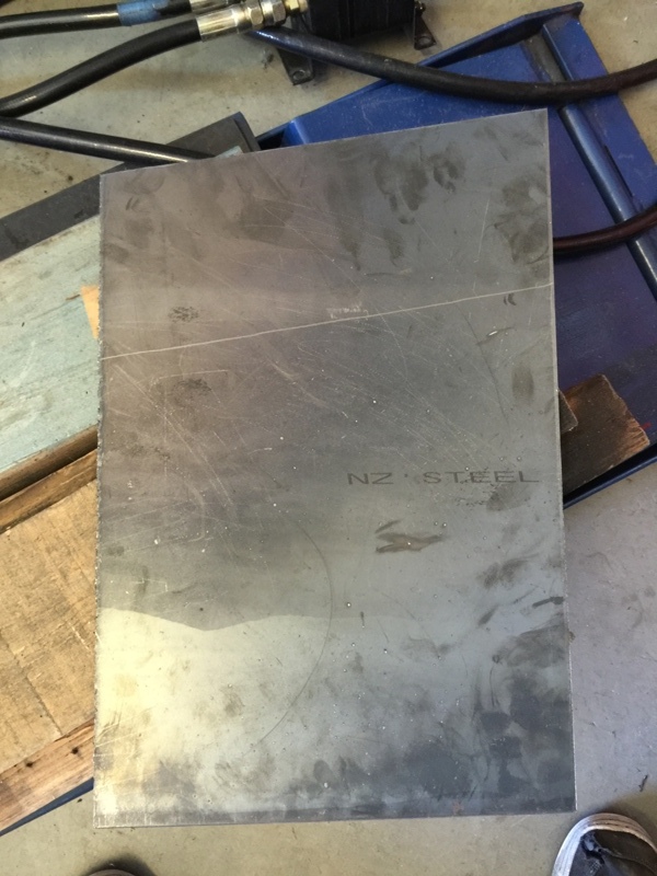
Started with some 1/8" mild steel plate. Traced the template onto the plate and fired up the plasma cutter. Ended up with this...

IMG_3927_zpspuvayjld.jpg


Used a 2" hole saw in the drill press to create the holes for the gauges. Also hit the face plate with the DA sander to clean it up a little.

IMG_3929_zpscqztrso7.jpg

IMG_3933_zpsnsswqgxj.jpg


Test fit with the hood before starting weld some legs on for the mounting system.

IMG_3936_zpsyjco9fvo.jpg


Used some 3/4" angle to make a bracket that gets bolted to the dash.

IMG_3941_zpszuf8tltl.jpg


A little truck bed liner sprayed on top of semi-gloss black. Did a little test fit... with and without the hood. I made the mount so that I can remove the hood pretty easily if I need to do some work on the gauges.

IMG_3952_zpsrplzala1.jpg

IMG_3961_zpszhafa87a.jpg


I did get the wires pulled up to the gauges, but that's about as far as I got.
 
I like the bed liner idea. I painted mine due to time constraints, but figured I would PC it later. I may have to try your idea. FYI, there are factory holes under your dash pad where the original cluster was bolted on for models that received them at the factory. I drilled an extra hole before I figured this out:bang:
As far as the gauge tilt goes, The one closest to the driver isn't a problem, but the middle and far gauge are difficult to read if the indicator is pointing past the 12 o'clock position. If you keep your mocked up locations it shouldn't be too much of an issue, unless your planning on turning the boost way up. Not sure where the normal indication is on a trans temp, but if it regularly reads past 190 degrees, then you won't see it very easily. I think I will be changing out my gauges for some isspro ones too, when I do, I will probably add some face plate angle thingies for the gauges to correct this.
On another note, I think I will be adding a water temp gauge. The oil pressure I have now is nice since my stock one quit, but having just drove over and back across the Rockies, water temp is one of the limiting issues when pulling up large hills. I can keep the boost below ten and the turbo outlet EGT's around 1000f, but the water temp will slowly rise and if your not careful they keep creeping. It would be nice to have one of those isspro water gauges with an alert light. Just some food for thought, you can always add and delete a gauge later. :beer:
 
....I will probably add some face plate angle thingies...

The gauges fit inside of 2" abs pipe. I had a piece in the garage and did a test fit. Worked perfect... nice and snug fit. The abs pipe has a slightly larger diameter than the gauge. The edge that butts up the back of the gauge face would need to be beveled or rounded in order to make it look finished. If I don't like the view of the gauges in their current location I'll be making some gauge angles. :) Thanks for the additional information...
 
Gauge pod done. Pyro and Boost are wired up. Got the back lighting and dimmer wired as well. Just in case anyone is wondering... I wired everything directly to 24v and they work just fine. The ISSPRO instructions don't say much about power supply voltage other than to connect them to the battery. Trans temp gauge will be wired up when I install the valve body in a month or so. I need to spend a little time getting the FJC ready for Rubithon, so going to have to pause on this project for a little while.

IMG_3973_zpsolpgm81q.jpg


I installed the dimmer adjustment at knee height on the left side of the steering wheel. You can see it in the picture below.

IMG_3986_zps41gemrkk.jpg
 
Extreme valve body arrived today... The folks down at Wholesale Automatics were super helpful and work fast. Also order a stereo and speakers... really tired of driving around without tunes. The pile of parts that need to be installed is starting grow, but don't have any time to work on it.

IMG_3994_zpswhodtfpc.jpg
 
I would think so, but I only have the hood so I've never seen the inside of the gauge pod.
 
Extreme Valve Body installed...

The installation was pretty easy, but this is a messy job. ATF everywhere... make sure you have plenty of cardboard on hand to line the garage floor. The kit from Wholesale Automatics comes with everything you need. Filter, gaskets, o-rings, etc are all included. You don't need to buy anything other than ATF. I decided to do a complete transmission flush while I was installing the valve body.

Here is the kit...

IMG_4101_zpsvekwiadh.jpg


Valve body...

IMG_4102_zpsgymgyhs4.jpg


The instructions that come with the kit are pretty good. They even include the bolt length for each location so you know which bolts go where during the install.

IMG_4104_zpsvufilxq8.jpg


A little "wholesale" bling... :D

IMG_4105_zpsz9cce5hu.jpg


After installing the valve body I turned to installing the transmission temperature sensor for the ISSPRO gauge. I decided to install the sensor in the stock location. The front line is the "out" line to the cooler. The oem sensor is mounted in the fitting that mounts to the transmission.

IMG_4108_zpsqyrm64e8.jpg


You can see the oem sensor in this picture...

IMG_4115_zpsae8jugy5.jpg


I removed the fitting from the transmission and removed the oem sensor.

IMG_4118_zpsqtxj7rhc.jpg


At the local parts supply store I found an M16x1.5 to 1/8 NPT reducer. This worked perfectly for the ISSPRO 1/8 NPT sensor.

IMG_4124_zpsddxew5iu.jpg

IMG_4125_zps7pwh6tfo.jpg


I installed the reducer into the fitting...

IMG_4127_zpseky1ulmh.jpg


Then reinstalled the fitting into the transmission and reconnected the hydraulic lines to the fitting... I ended up zip-tying the oem sensor wire up to the wiring harness on top of the transmission.

IMG_4131_zpsp7xczch8.jpg


I ran all the electrical wiring to the sensor and connected it back to the trans temp gauge. Everything worked as expected.

My impressions after the first drive. WOW! Very different and noticeable shifting pattern from the slushbox. I haven't driven more than a few miles, but the shifting is much firmer and very quick... no long lags between shifts. I was a little concerned about the shifting being abrupt as I had read in a few other threads. So far I really like the shifting. It's nice to press on the go-go pedal and have the transmission respond.
 
Next I need to start wiring up the 12v house battery. This arrived today... :D New Pioneer head unit and new dash face plate. Looking forward to having tunes.

45093a99-8494-44b6-93f7-3bc3124f31f3_zpsmmwooagm.jpg
 
I've been driving the heck out the 70 and loving every minute of it. Decided to start on the sliders. Using 2x2x.120 square tube and some 1.75x.120 wall tube. I haven't figure out a good way to work around on the exhaust, but started making a skid plate that might turn into the front leg. I might end up in the scrap bin if this doesn't work.

Started with a bunch of cardboard... then move to a piece of .250" plate... cut this out. Plan is to bend it to fits around the exhaust.

IMG_4579_zpsmkjdvwkm.jpg


First couple of bends...

IMG_4580_zpspqjca6yq.jpg


Ended up with this... it bolts to the frame. I had to drill a couple of holes in the frame as well.

IMG_4584_zpsnnlhtily.jpg

IMG_4588_zpssbtwflsv.jpg

IMG_4595_zps9dkpaeza.jpg


Then I moved on to the sliders... created my template.

IMG_4609_zpsfcl05q54.jpg


Square tube base with round tube outer...

IMG_4611_zpsv2kxpdut.jpg


Cut and notched the tube...

IMG_4612_zpsowpkdlqk.jpg


Here one of the sliders tacked together...

IMG_4627_zps7zvhlnjq.jpg


Test fit...

IMG_4614_zps9hilubv0.jpg


I wanted a step... so I added a small bump out. This will eventually get cover with a piece of plate steel...

IMG_4616_zpswofbnh8q.jpg


IMG_4620_zpsq7grhhgj.jpg


IMG_4621_zps7ccxw08x.jpg


IMG_4626_zpszsi1i2bb.jpg


Now I will start working on the legs... and finish the thought on the exhaust skid... :)
 
Didn't get much done today, but hoping to get a little more time on the sliders tomorrow.

Trying to add some reinforcement to the skid plate that wraps the exhaust. Started by cutting out a piece of plate, then cutting a couple of holes in it.

IMG_4646_zpsny90q557.jpg


IMG_4651_zpsg8i5kqni.jpg


Then sliced it in half. Test fit. The idea is that I will get this to fit nice and snug. The bottom section will get welded in place. I will drill a hole through both plates, weld a nut to the inner plate. Then once on the truck I will bolt the top section into place for some additional strength.

IMG_4652_zps4hmftsvp.jpg


IMG_4653_zpsxrboybp6.jpg


Temporarily tacked in place. I also plan on putting a few holes in the skid plate, so water drains out. Still lots of trimming and cleanup to do.

IMG_4654_zpsysvljela.jpg


More tomorrow...
 
Got a little time to finish up the other end of the skid plate... I feel like I'm spending too much time on this part of the sliders... stupid exhaust system!

Front section cut out.

IMG_4662_zpsrdvsyf2d.jpg

IMG_4665_zpscg8vvejd.jpg


Did a test fit and installed it on the truck... clearances are pretty tight. Might need to hit it with a grinder in a few spots.

IMG_4667_zpsvkfpyu6e.jpg

IMG_4682_zpsimuo74rg.jpg


Then I burned the end plates into place... no making fun of my crappy welds. :p

IMG_4684_zps2up7mo8t.jpg


Welded some nuts on the back side...

IMG_4688_zpsmmbqgv4w.jpg


I did a final test fit... but I need to do a little more trimming to make things fit. There isn't enough clearance between the body. Once I get this thing trimmed and fitting nice... I will start working on the legs for the sliders. Maybe next weekend.
 

Users who are viewing this thread

Back
Top Bottom