Look what I found.... 1961 FJ40 FST (2 Viewers)

This site may earn a commission from merchant affiliate
links, including eBay, Amazon, Skimlinks, and others.

aussie25 - is hzj78 troopy equivalent to a hzj79 ute? i really need a front diff for one of these at the right price (and closer to home!) and hj45 is a h diesel and hj47 a 2h diesel; have i got that right?

cult45 - thanks for the link; very informative

quick play tonight. got bezel off. harder than it sounds; 2 remaining screws very reluctant. also 2 broken screws (one of them mine). got one out; other eluding me but i will get it. top bezel screws had remnants of a rubber spacer between the bezel and the bib. anyone know if there should be 2 of these, or 4, or is it a po mod? anyways nice to be turning a spanner again.

pondered the column shift pita and did a little study. i have a 1965 parts book in folder style; think others have the same book

010.JPG
 
anyways, this has an exploded view of the "control shaft and linkage" in both left and right hand drive.

however quiet a different unit to my 1961 example.

i try some pics

003.JPG


above my 61 "bracket, control shaft lower"

008.JPG


and above same from my 1965 book.

009.JPG


this a wider view of lhd in my 65 book
 
i have been considering the option of sourcing a serviceable lhd assembly and seeing if it can be dismantled/modified/reassembled (perhaps using some of my original 61rhd components) to make something i can use. however i wasn't really ready for a change in the structure of the whole assembly! just ignorantly thought it probably the same throughout the 60s. (remembering australia only got column shift in 61/62 and they just do not exist here) anyone know when this change occured?? is it reasonable to assume the change occured with the new generation of the gearbox in early63??

i am sold on the idea of repairing my original 61 box but... its all a bit pointless unless i have the column assembly to activate it. and i can't imagine pre 63 assemblies are easy to find anywhere; let alone australia. pondering pondering but this is a real pain. sure i have the rest of this old tojo sorted.

any thoughts greatly appreciated
 
Hmm I'm afraid I can't be of much help. I don't have a 61-62 parts book. Only thing I can offer you is get the linkage out and make a drawing so that you can reproduce it. But then you first have to know if lhd or rhd is different. Anyone with a early parts book maybe?

About the stuff on the column: we had the steering column out but don't remember what we did with the shift arm. I think we didn't touch it. But I think you can get it out downwards. (But then the steering wheel has to get of I'm afraid). When you get it out you can try to make it work on the workbench. Good luck.
 
red that is great; thank you muchly! if it not too much to ask is there any chance you could post up the corresponding part numbers to match the 2 diagrams? doesn't really matter if part numbers are in the obsolete format it just means then i can figure what is actually different rhd v lhd. and then i can try figure why. i'v really know idea how this assembly actually operates; ie what the moving/connecting parts are. or how it possibly comes apart (once i get it out that is !)

the pin (part L in both diagrams) is a great clue; going to look for that tomorrow.

anyways thanks again.

quick play tonight. fitted a grease nipple to my "control shaft lower bracket". a little surprised to be able to get some grease through the lower bracket

012.JPG
 
next to the grease nipple are 2 stud holes. what purpose do they serve?

anyways a play with the hydraulics after that. gave everything a hone. its all gonna be good to go. all 8 wheel cyls are serviceable. going to swap out one master cyl for a better unit but got that covered. just need to do some brake parts shopping. also started cleaning everything else to do with the brakes on the wire wheel. outside of wheel cyls, pistons, springs, adjusters, bolts, bleed screws etc etc. more cleaning to be done but don't think any of this going to be a problem.

thinking to ask elsewhere on mud re my column assembly for those who don't frequent the 25 hollow. but guessing anyone with stuff this old drops in here from time to time!
 
Those stud holes seem to have no function.
image.jpg
Maybe for an optional back-up lamp?

image.jpg
When you move the lever on the column up and down you shift between 2nd an 3rd. In that case the lower arm (left on this pic) turns up and down. When you lift the lever on the column the shaft moves up and the upper (right) arm turns to shift between 1st and reverse.

In the transmission is a lock that blocks one lever when the other is in gear. I think there is also some lock or a sleeve in here to prevent shifting two gears at the same time. Part L must be inside the housing.
 
haha cheers bumstein!

yea needs more work than im ever likely to give it! nice yard ornament i suppose; been there a long time. i have heard that the old crysler sidevalve 6 didnt change a lot over the years; ie a motor decades newer should bolt in? chrysler ran sidevalve until the early 60s in aust. havent studied any of this myself though.

red - thanks heaps for that info you posted. most stuff seems the same lhd v rhd. mainly the bare lower block and outer tube it seems to me. i have a good lead on an aussie shorty forty wreck with later box but the column assembly still in situ. sweating on that being a goer but its miles away and a few logistics involved.

havent played much lately. been renovating a house for my sister in law; reminds me how much paint of any description bores me! my good mate went to the city (6hrs away) for a few days yesterday so sent him with a list, sample wheel cyl, and a very slim wad of cash. heres hoping he returns with enough treasure to get project shorty back to 'roller' status. im gonna claim it as financial commitment.
 
Nice guys thanks for sharring but now you have me wondering on the trailer type buck board sitting behind the old Chrysler. :)
:beer:
 
ozcruiser - the trailer is a homemade horse drawn contraption that was the personal chattels of another old station employee; a full blood aboriginal who lived his entire life on this station. it is based on an old buick front axle; possibly quiet early. a copy of the west australian vehicle registration list exist from 1916 or 1919 (i think the former) and it lists a buick registered to my family at this address at that time. however no other trace of the buick seems to exist so this axle could be from anywhere. wouldnt take much study i suppose.

anyways had no time to play lately. have a swivel kit in my possession i hope fits and enough wheel cyl boots and buckets to make a start at least. would rather tackle the swivel hubs when i have a spare day and can do it in one sitting.

popped hat off rear diff; mighty clean and in order so sealed that up and will worry about rear axle seals down the track if they give trouble.

and got steering wheel off. my puller simply tore the remaining rusty old threads out of the steer wheel centre. put a small slice of pipe over the centre, wrapped that in a wet rag to protect the wheel itself and used a little heat. mocked up in the pic below.

014.JPG
 
some weeks later got it off. basically flogged centre spline with a copper hammer (using unwound nut to protect the thread) and with a bloke pulling each side it came quiet easily. maybe the heat helped i dunno. anyway all this in aid of getting my pita column assembly out.
008.JPG
954081[/ATTACH]

so next is the cast alloy piece that locates the turn signal etc. i presume in a normal unsiezed column assembly world it can simply unscrew with the gearshift pulled towards you??
 
thinking to just sacrifice the cast alloy lump PRESUMING THEY ARE THE SAME AS LATER YEAR LANDCRUISERS??

to this end went and studied a 64 wreck i have (pics in the latter part of my project patina thread) that very conviently came without a steering wheel....
have been unable to compare them side by side yet

001.JPG

so now to get this one off. my parts wreck has the turn indicator assembly (which i plan to put in the 61 where it is missing) but how to dismantle?

003.JPG

surely i dont have to drive out the pin in the centre of above pic?? it must be just stuck tight where flattened part enters the block on the steer wheel side of the pin??
 
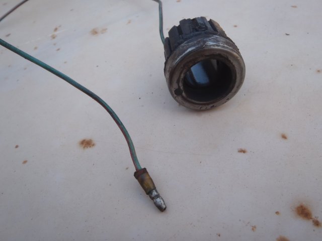
once again any help appreciated; i have never had any of this sort of stuff apart before. while playing with all this on the parts wreck removed and inspected the horn contact base or whatever it may be called. seems in much better condition than the 61 original. all very new to me but anyway this is what it looks like

004.JPG
 
In the US market the turn signal stayed the same until the 73 model. In the 40/55 section some had a thread about replacement for the switch/rod/cap/handle still available new from Toyota. This was LHD so would have to check the availability for the RHD. Only difference I noticed was the handle was painted black instead of the polished pot metal. The 64 replacement you found is missing the two little spring loaded levers that cancel the turn signal when you turn the other direction. You can see the posts they pivot on above and below the handle.

Here is the thread I mentioned https://forum.ih8mud.com/threads/early-turn-signal-switch-part-number.807520/#post-9218699
 
thinking to just sacrifice the cast alloy lump PRESUMING THEY ARE THE SAME AS LATER YEAR LANDCRUISERS??

surely i dont have to drive out the pin in the centre of above pic?? it must be just stuck tight where flattened part enters the block on the steer wheel side of the pin??

Please don't sacrifice the cast alloy lump. To remove the assy., there's a phillips head screw on the pax side of said lump. Once this is unscrewed, sit in the driver's seat and reef said cast alloy lump towards oneself. The connecting rod will fall out as it is separated from said cast alloy lump.
 
Last edited:

Users who are viewing this thread

Back
Top Bottom